


ELECTRICAL DATA S3F80P5_UM_ REV1.00
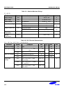
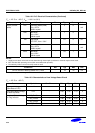
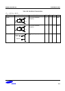
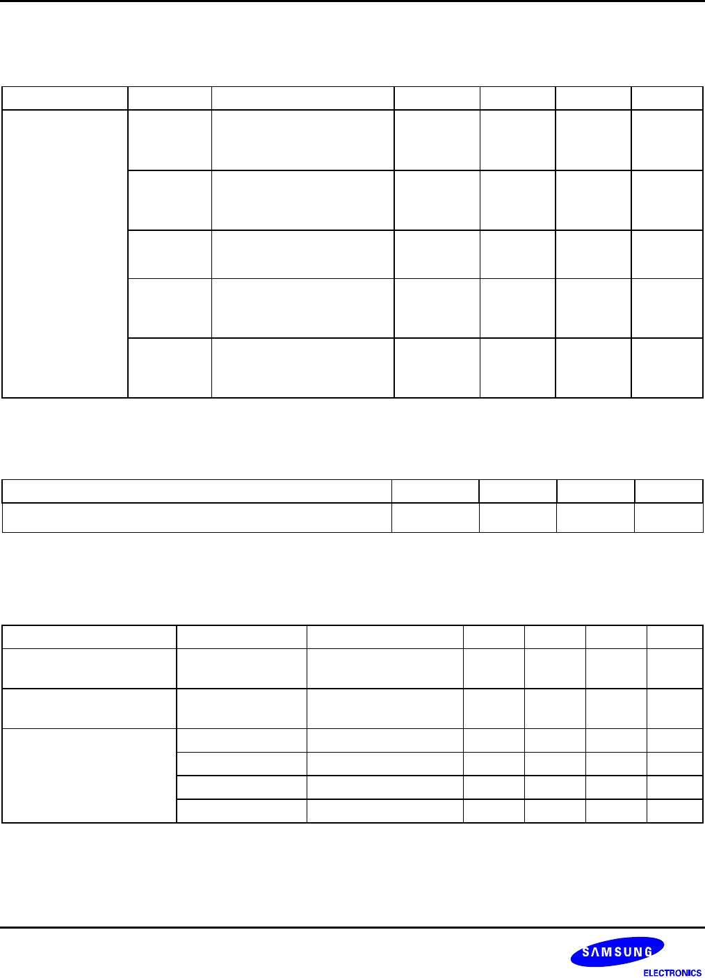
Table 16-2. D.C. Electrical Characteristics (Continued)
(T
A
= -25 °C to + 85 °C, V
DD
= 1.60 V to 3.6 V)
Parameter Symbol Conditions Min Typ Max Unit
I
DD1
Operating Mode
(note2)
V
DD
= 3.6 V
8 MHz crystal
−
3
6
mA
I
DD2
Idle Mode
V
DD
=3.6 V
8 MHz crystal
−
1
2
I
DD3
Stop Mode
LVD OFF, V
DD
= 3.6 V
−
0.7 5 uA
I
DD12
Operating Mode
V
DD
= 3.6 V
4 MHz crystal
−
1.5
3
mA
Supply Current
(note1)
I
DD22
Idle Mode
V
DD
=3.6 V
4 MHz crystal
−
0.5
1
NOTES:
1. Supply current does not include current drawn through internal pull-up resistors or external output current loads.
2. IDD1 includes flash operating current (flash erase/write/read operation).
3
. The adder by LVD on current in back-up mode is 18uA.
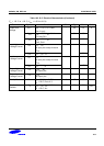
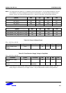
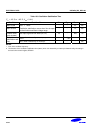
Conditions Min Typ Max Unit
LVD on current in back-up mode V
DD
= 1.60V
−
18 35 uA
Note) Back-up mode voltage is VDD between LVD and POR.
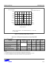
Table 16-3. Characteristics of Low Voltage Detect Circuit
(T
A
= -25 °C to + 85 °C)
Parameter Symbol Conditions Min Typ Max Unit
Hysteresis Voltage of LVD
(Slew Rate of LVD)
ΔV −
– 100 200 mV
Low Level Detect Voltage
for Back-Up Mode
LVD
−
1.60 1.65 1.70 V
LVD_FLAG1
−
1.78 1.88 1.98 V
LVD_FLAG2
−
1.88 1.98 2.06 V
LVD_FLAG3
−
2.43 2.53 2.63 V
Low Level Detect Voltage
for Flag Indicator
LVD_FLAG4
−
2.63 2.73 2.83 V
16-4