


-E11-
R-AUDIO-L VIDEO
AUDIO
VIDEO
INPUT
1
3
4
RF OUTPUT
CHANNEL
VIDEO
S-VIDEO AUDIO
ANTENNA
COMPONENT VIDEO OUT
L
R
AV 1 IN
VIDEO
S-VIDEO
AUDIO
DIGITAL
AUDIO
L
R
OUT
OUTIN
S-VIDEO IN 1
O
NENT VIDEO OUT
VIDEO
S-VIDEO
AUDIO
DIGITAL
AUDIO
L
R
OUT
COMPONENT VIDEO INPUT
YP
B
P
R
COMPONENT VIDEO OUT
VIDEO
S-VIDEO
A
DIGITAL
AUDIO
OU
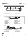
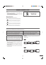
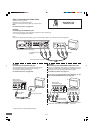
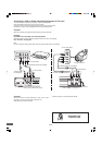
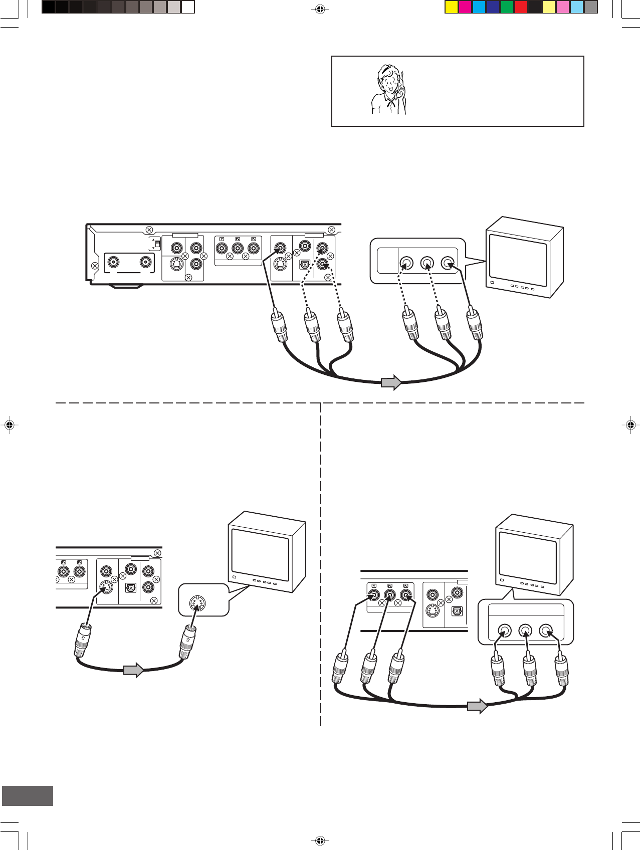
Step 2: Connecting the Video Cable
Connect the unit to your TV.
Select one of the following examples.
(If the TV has an antenna input jack only, skip this step.)
Note:
For AUDIO connection, see page E12.
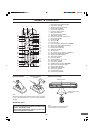
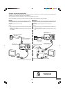
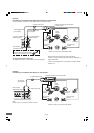
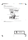
Example:
Connecting to the S-VIDEO OUT jack
Connect the S-video cable (not supplied) as shown below.
(The VIDEO OUT jack connection is not necessary.)
You can enjoy clearer picture images.
For AUDIO connection, see page E12.
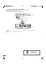
Example:
Connecting to the COMPONENT VIDEO OUT jacks
Connect a component video cable (not supplied) as shown
below. (The VIDEO OUT or S-VIDEO OUT jack connection is not
necessary.) You can enjoy high quality picture images.
For AUDIO connection, see page E12.
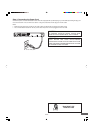
If you use a TV with Progressive-scan Capability, set the
unit to the PROGRESSIVE mode. See page E44.
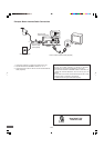
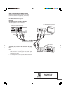
DVD recorder (Partial back panel)
To VIDEO OUT jack
(Yellow)
Audio/Video cable (supplied)
(Yellow)
TV
DVD recorder
(Partial back panel)
To S-VIDEO
OUT jack
To S-video input jack
*S-video cable (not supplied)
* Please consult your local audio/video dealer.
To COMPONENT
VIDEO OUT jacks
To component video
input jacks
TV
*Component video cable (not supplied)
Example:
Connecting to the VIDEO OUT jack
Connect the yellow plug of the Audio/Video cable to the video (yellow) jack.
You can enjoy standard picture images.
Note:
Connect the right (red) and left (white) plugs of the Audio/Video cable to the audio input jacks (see page E12).
Need help? Call
1-800-813-3435
DVD recorder
(Partial back panel)
Green
Blue
Red
TV