-E5-
2 3 451 6 7 8 9
101112
3
4
RF OUTPUT
CHANNEL
VIDEO
S-VIDEO AUDIO
ANTENNA
COMPONENT VIDEO OUT
L
R
AV 1 IN
VIDEO
S-VIDEO
AUDIO
DIGITAL
AUDIO
L
R
OUT
OUTIN
4 53 61 2
CDST
s
DIGITAL
RW TITLE CH CHP SHUFF PROG REP 1 ALL A-B REC
SAP TV
HQ SP LP EP
+
101 2 4 5 6 7 8 1193
13
141516
18
17
19
12
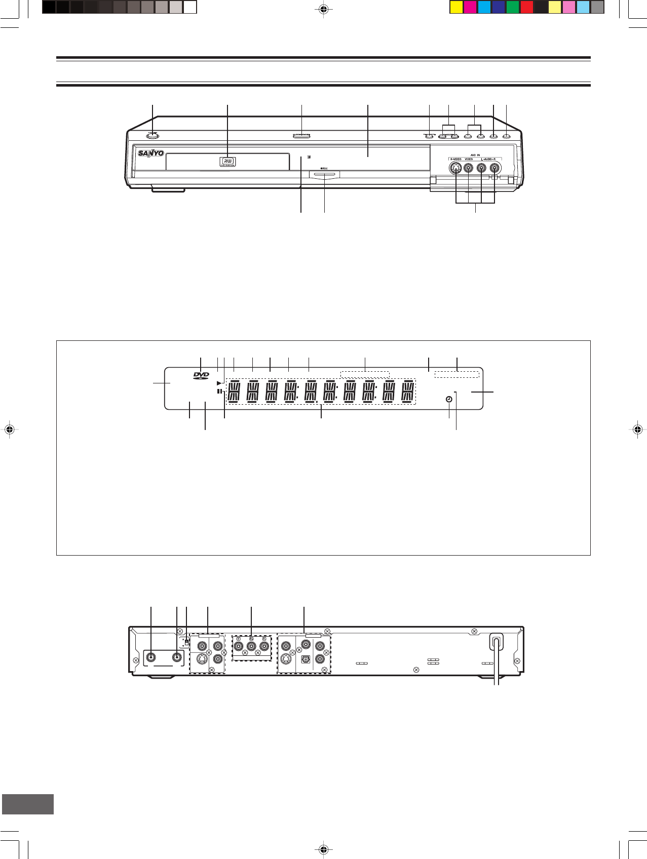
Front Panel
CONTROLS
1. Power button (POWER)
2. Disc tray
3. Open/Close button (q OPEN/CLOSE)
4. FL display
5. Record mode button (REC MODE)
6. TV channel scanning button (- CHANNEL +)
7. Skip/Next/Previous buttons (f , e)
8. Stop button (n)
9. Play button (a)
10. 2nd AV input jacks (AV2 IN)
S-video input jack (S-VIDEO)
Video input jack (VIDEO)
Audio input jacks (L-AUDIO-R)
11. Record button and indicator (m REC)
12. Remote sensor (IR)
FL Display
11. Record mode indicators (HQ, SP, LP, EP, +)
12. TV indicator (TV)
13. Second Audio Program indicator (SAP)
14. Timer indicator (0)
15. Message or number indicators
(Title, chapter, track, playing time or other information)
16. Pause indicator (k)
17. CD indicator (CD)
18. Stereo indictor (ST)
19. Dolby Digital indicator (s DIGITAL)
Back Panel
1. VHF/UHF antenna input jack (ANTENNA IN)
2. VHF/UHF antenna output jack (ANTENNA OUT)
3. RF output channel switch (RF OUTPUT CHANNEL)
4. 1st AV input jacks (AV1 IN)
Video input jack (VIDEO)
S-video input jack (S-VIDEO)
Audio input jacks (L/R AUDIO)
1. DVD indicator (DVD)
2. DVD rewritable indicator (RW)
3. Play indicator (a)
4. Title indicator (TITLE)
5. Channel indicator (CH)
6. Chapter indicator (CHP)
7. Shuffle indicator (SHUFF)
8. Program indicator (PROG)
9. Repeat indicators (REP1, ALL, A-B)
10. Record indicator (REC)
5. Component video output jacks (COMPONENT VIDEO OUT)
6. AV output jacks (OUT)
Video output jack (VIDEO)
S-video output jack (S-VIDEO)
Coaxial digital audio output and Optical digital audio output
jacks (DIGITAL AUDIO)
Audio output jacks (L/R AUDIO)


