


20
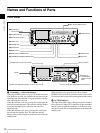
Names and Functions of Parts
Chapter 1 Overview
To handle input signals as non-audio data, use the AUDIO
CONTROL >DATA MODE item of the setup menu (see
page 93) to set the input of channels 1 and 2 (CH1/CH2
IN) or the input of channels 3 and 4 (CH3/CH4 IN) to
“DATA”.
b DIGITAL AUDIO (AES/EBU) OUTPUT 1/2 and
3/4 connectors (BNC type)
These output AES/EBU format digital audio signals. The
1/2 connector corresponds to audio channels 1 and 2, and
the 3/4 connector corresponds to audio channels 3 and 4.
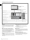
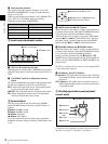
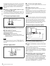
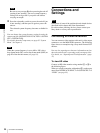
5 Timecode input/output section
a TIME CODE IN connector
Inputs SMPTE timecode generated by an external device.
b TIME CODE OUT connector
Outputs the following timecode, depending on the
operating state of the unit.
During playback: Playback timecode
During recording: The timecode from the internal
timecode generator or the timecode input to the TIME
CODE IN connector.
In E-E mode no timecode is output if TIME CODE >EE
OUT PHASE in the setup menu is set to “MUTING” (see
page 90).
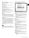
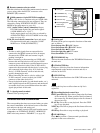
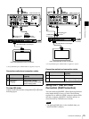
6 Power supply section
a -AC IN (AC power input) connector
Connect to an AC power supply with the power cord (not
supplied).
b POWER (main power) switch
Press the + side to power on the unit. Press the a side to
power off.
When using the unit, normally leave the POWER switch in
the + (on) position, and use the on/standby switch on the
front panel to switch the unit between the operating state
and standby state.
If you press the on/standby switch on the front panel while
the unit is in the operating state, the unit saves its data and
then enters the standby state (the on/standby indicator
lights red). Before turning the main power off, always
check to be sure that the unit is in the standby state, and
then push the main power switch to the a side.
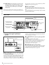
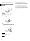
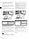
7 External device connection section
a CONTROL connector (minijack 4-pole)
Connect the optional RM-LG2 Remote Control Unit.
b RS232C (serial interface) connector (D-sub 9-pin,
male)
Connect a computer or other device with a serial interface
to control this unit from that device.
When you use this connector, set the remote connector
selector switch to the RS232C side, and set INTERFACE
SELECT >REMOTE I/F in the setup menu to “9PIN/RS-
232C” (see page 94).
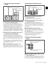
c REMOTE(9P) (remote control 9-pin) connector
(D-sub 9-pin, RS-422A compliant, female)
To control this unit from a controller or VTR supporting
the RS-422A Sony 9-pin VTR protocol, connect the device
to this connector. When you use this connector, set the
remote connector selector switch to the REMOTE(9P)
side, and set INTERFACE SELECT > REMOTE I/F in the
setup menu to “9PIN/RS232C” (see page 94).
Note
TIME CODE
IN OUT
1 TIME CODE IN connector
2 TIME CODE OUT connector
POWER
-AC IN
1 - AC IN connector
2 POWER switch
Note
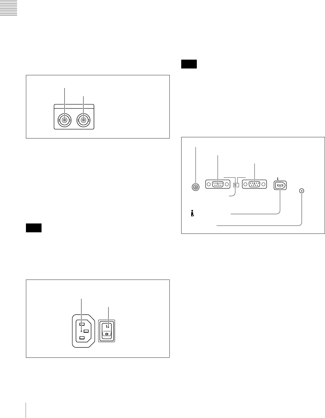
RS232C REMOTE(9P)
CONTROL
S400
1 CONTROL connector
2 RS232C connector
3 REMOTE(9P) connector
4
Remote connector
selector switch
5 S400 connector
6 U terminal