


29
Connections and Settings
Chapter 2 Preparations
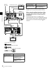
For details about the settings of the DSR-2000A/2000AP,
refer to the operating instructions for that unit.
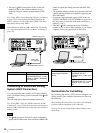
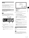
Editing Control Unit Settings
When connecting an editing control unit to use with this
unit, make the following settings.
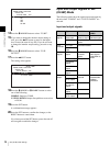
BVE-700/700A
Set VTR constants as follows.
Remote Control Unit Settings
You can control this unit from an RM-280 Remote Control
Unit.
Connect this unit to the RM-280 with a 9-pin remote
control cable (not supplied), and make the settings in the
following table.
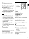
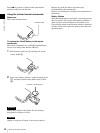
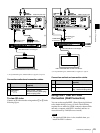
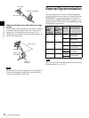
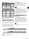
Using XLR Cables (Audio Cables)
Before connecting XLR cables to this unit's analog audio
input and output connectors, always attach the supplied
ferrite cores to the XLR cables. Attach as shown below.
To attach the ferrite core
Loop the XLR cable one time through the ferrite core, on
the side closest to the connector that is connected to this
unit, and fix the ferrite core at the specified position.
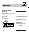
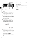
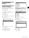
DSR-2000A/2000AP
(recorder) settings
This unit’s (player) settings
i.LINK button: Lit Remote control switch:
REMOTE
SDTI/i.LINK button: i.LINK Set the setup menu item
INTERFACE SELECT
>REMOTE I/F to “i.LINK” (see
page 94).
SDSDI OUTPUTHDSDI INPUT
AUDIO INPUT
HDSDI OUTPUT
12
REF VIDEO INPUT
TIME CODE
POWER
ANALOG HD INPUT
DIGITAL
AUDIO
(AES/EBU)
COMPOSITE OUT AUDIO MONITOR
1/3 2/4
AUDIO OUTPUT
1/3 2/4
R L IN OUT
Y/G P
B /R
SYNS
RS232C REMOTE(9P)
PB /B
1/2
INPUT
OUTPUT
CONTROL
3/4
1/2 3/4
S400
-AC IN
MONITOR
MONITOR
AUDIO
i.LINK
VIDEO OUT 3
(SUPER)
S400
COMPOSITE
OUT
AUDIO
MONITOR
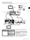
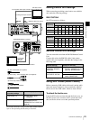
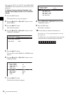
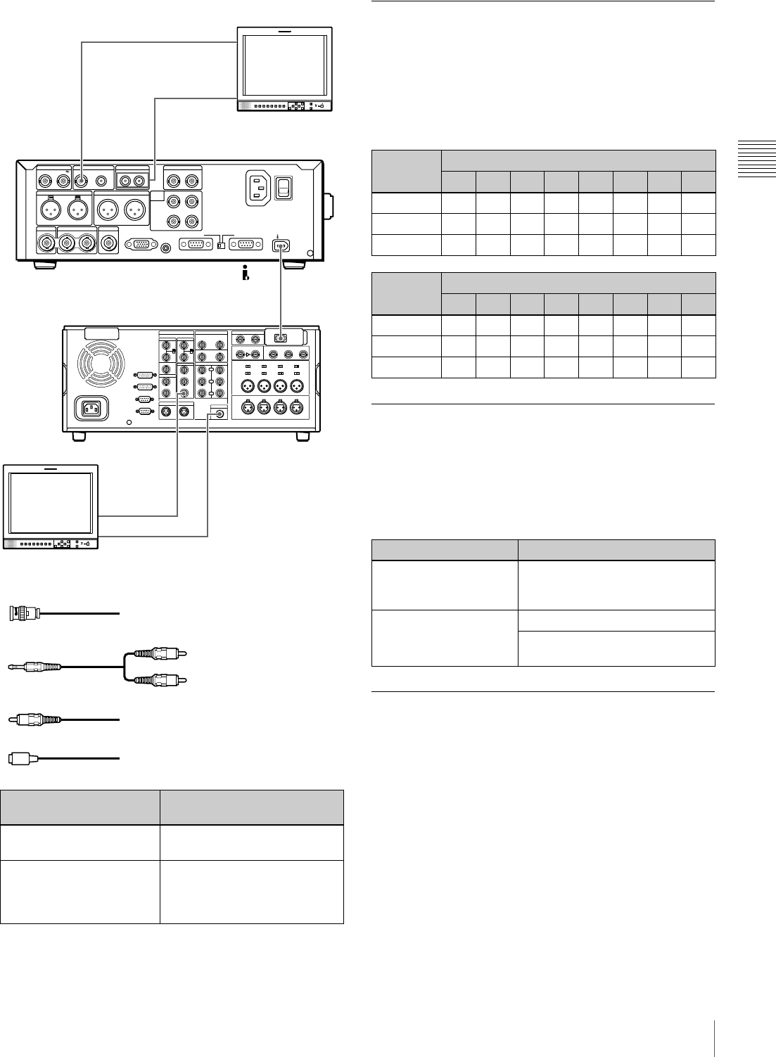
To analog audio input connector
PDW-F70 (this unit, player)
1
2: Phono plug – stereo miniplug cable (not supplied)
3: Phono plug cable (not supplied)
To composite
video input
connector
DSR-2000A/2000AP (recorder)
SD video monitor
SD video monitor
To composite video input connector
To analog audio input connector
2
4
1: 75Ω coaxial cable (not supplied)
4: i.LINK cable (not supplied)
1
3
System
frequency
VTR CONSTANT 1
1 2 3 4 5 6 7 8
30P/60I A093009616160380
25P/50I A193007D16160380
24P A293007816160380
System
frequency
VTR CONSTANT 2
1 2 3 4 5 6 7 8
30P/60I 0A07FE00805AFF5A
25P/50I 0A07FE00804CFF4B
24P 0A07FE008048FF48
RM-280 settings Settings on this unit
EDITOR/REMOTE
CONTROL: REMOTE
CONTROL
Setup menu item INTERFACE
SELECT >REMOTE I/F (see
page 94): 9PIN/RS-232C
Setup menu item 19
FNC MODE: XDCAM
Remote control switch: REMOTE
Remote connector selector
switch: REMOTE(9P)