


37
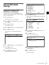
Superimposed Text Information
Chapter 2 Preparations
Superimposed Text
Information
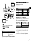
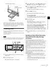
The HDSDI signals output from the HDSDI OUTPUT 1
and 2 connectors and the MONITOR connector, the
SDSDI signals output from the SDSDI OUTPUT
connector, and the composite signals output from the
COMPOSITE OUT connector can contain superimposed
text information, including timecode, menu settings, and
alarm messages.
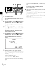
To turn superimposed text on and off
Set the CHAR SEL item on page P1 of the function menu.
ON: Display superimposed text.
OFF: Do not display superimposed text.
LCD: Display superimposed text on the LCD panel of this
unit, but do not display it on an external video monitor
connected to this unit.
Even when ON is selected, you can forcibly turn off the
superimposition of character information in HD output by
setting the SETUP MENU >DISPLAY CONTROL >HD
CHARA item.
Adjusting the text display
You can use the items in the DISPLAY CONTROL setup
menu to specify the position, size, and type of
superimposed characters.
See page 88 for more information about the items in the
DISPLAY CONTROL menu.
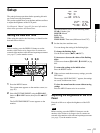
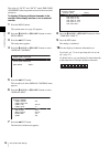
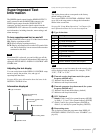
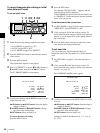
Information displayed
a) Only when the system frequency is 60I/30P.
The display shown above corresponds to the factory
default settings of the unit.
You can use DISPLAY CONTROL >DISPLAY INFO
(page 89) in the setup menu to change the information
shown in the second line.
See page 96 “Setup Menu Operations” in Chapter 6 for
more information about how to use the setup menu.
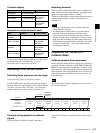
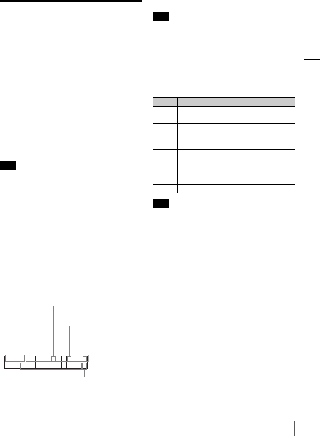
a Type of time data
If the time data or user bits cannot be read correctly, they
will be displayed with an asterisk. For example, “T*R”,
“U*R”, “T*R.” or “U*R.”.
b Timecode reader drop-frame mark (for system
frequency 60I/30P only)
“.”: Indicates drop-frame mode
“:”: Indicates non-drop-frame mode
c Timecode generator drop-frame mark (for system
frequency 60I/30P only)
“.”: Indicates drop-frame mode (factory default)
“:”: Indicates non-drop-frame mode
d VITC field mark
“ ” (blank): Fields 1 and 3 (for system frequency 60I/30P)
or fields 1, 3, 5 and 7 (for system frequency 50I/25P)
“*”: Fields 2 and 4 (for system frequency 60I/30P) or
fields 2, 4, 6 and 8 (for system frequency 50I/25P)
e Menu setting states
This is displayed when the setup menu item DISPLAY
CONTROL >MENU STATUS is set to “ENABLE” (see
page 89).
Note
TCR 00:04.47.07*
PLAY LOCK
1 Type of time data
2 Timecode reader drop
frame mark
a)
3 Timecode generator drop
frame mark
a)
4 VITC field mark
5 Menu setting states
6 Operation mode
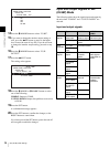
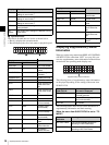
Time data
Note
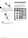
Display Meaning
CNT Counter data
TCR TC reader timecode data
UBR TC reader user bits data
TCR. VITC reader timecode
UBR. VITC reader user bits data
TCG TC generator timecode
UBG TC generator user bits data
IN In point time data
OUT Out point time data
DUR Duration between In point and Out point
Note