


26
Connections and Settings
Chapter 2 Preparations
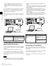
• This unit’s S400 connector has 6 pins. Check the
number of pins on the i.LINK connector of your
notebook computer, and use an appropriate i.LINK
cable.
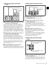
See “Using PDZ-1 Proxy Browsing Software” in Chapter
4 (page 74) for more information about installing the
PDZ-1 software. See the online help of PDZ-1 for more
information about using PDZ-1.
Some limitations apply to FAM connections. For details,
see “File Operations in File Access Mode” in Chapter 5
(page 78).
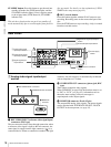
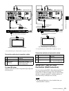
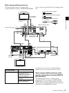
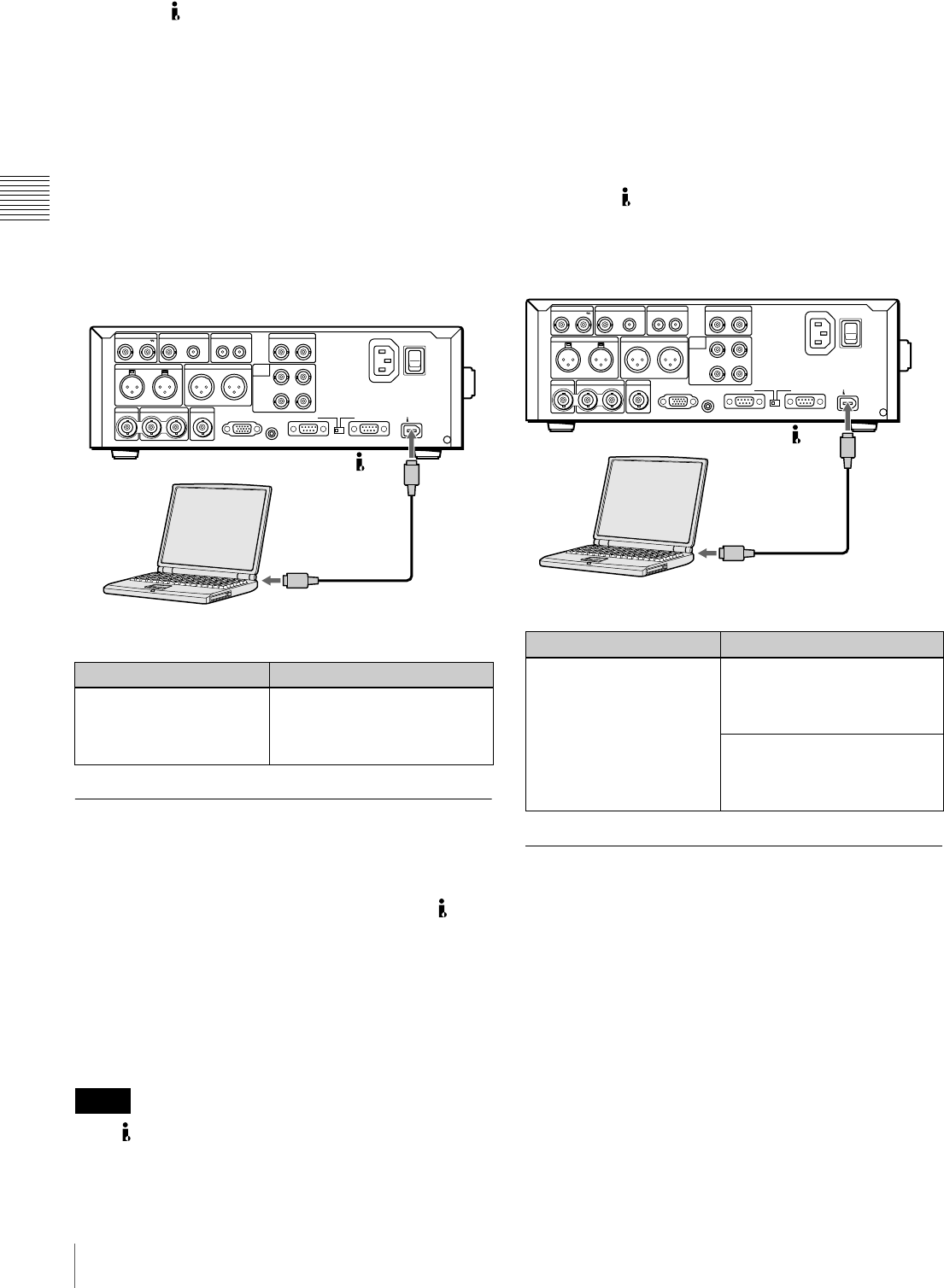
Connecting to a Nonlinear Editing
System (AV/C Connection)
You can send video/audio signals (AV/C data) from this
unit to a nonlinear editing system connected to the S400
connector.
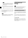
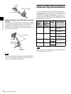
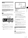
The following figure shows an example connection.
See “Using PDZ-1 Over an i.LINK Connection (FAM
Connection)” (page 25) for the connections and settings to
make a FAM connection between this unit and a nonlinear
editing system.
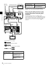
• The S400 connector of this unit outputs video/audio
signals in DVCAM format. Data recorded in MPEG HD
format is output after being converted into DVCAM
format.
• The nonlinear editing system to be connected to this unit
requires editing software (not supplied) supporting the
DVCAM format.
• To transfer video and audio signals (AV/C data), use
AUDIO CONTROL >DV OUT MODE (see page 93) in
the setup menu to select the audio mode (the factory
default is “2ch”).
• This unit’s S400 connector has 6 pins. Check the
number of pins on the i.LINK connector of your laptop
computer, and use an appropriate i.LINK cable.
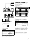
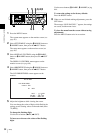
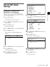
Connections for Cut Editing
By connecting this unit to a VTR, you can configure a cut
editing system. Some example connections are shown in
the following.
When making the connections, also refer to the manuals
provided with the equipment to be connected.
See page 29 for more information about editing control
unit settings.
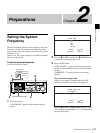
On the computer On this unit
Install PDZ-1. Set the setup menu item
INTERFACE SELECT >i.LINK
MODE to “FAM(PC REMOTE)”
(see page 94).
Notes
SDSDI OUTPUTHDSDI INPUT
AUDIO INPUT
HDSDI OUTPUT
12
REF VIDEO INPUT
TIME CODE
POWER
ANALOG HD INPUT
DIGITAL
AUDIO
(AES/EBU)
COMPOSITE OUT AUDIO MONITOR
1/3 2/4
AUDIO OUTPUT
1/3 2/4
R L IN OUT
Y/G P
B /R
SYNS
RS232C REMOTE(9P)
PB /B
1/2
INPUT
OUTPUT
CONTROL
3/4
1/2 3/4
S400
-AC IN
MONITOR
S400
PDW-F70 (this unit)
i.LINK cable
(not supplied)
i.LINK (IEEE1394) connector
Laptop computer
On the computer On this unit
Install editing software
supporting the DVCAM
format.
Set the setup menu item
INTERFACE SELECT
>REMOTE I/F to “i.LINK” (see
page 94).
Set the setup menu item
INTERFACE SELECT >i.LINK
MODE to “AV/C” (see page
94).
SDSDI OUTPUTHDSDI INPUT
AUDIO INPUT
HDSDI OUTPUT
12
REF VIDEO INPUT
TIME CODE
POWER
ANALOG HD INPUT
DIGITAL
AUDIO
(AES/EBU)
COMPOSITE OUT AUDIO MONITOR
1/3 2/4
AUDIO OUTPUT
1/3 2/4
R L IN OUT
Y/G P
B /R
SYNS
RS232C REMOTE(9P)
PB /B
1/2
INPUT
OUTPUT
CONTROL
3/4
1/2 3/4
S400
-AC IN
MONITOR
S400
Laptop computer
i.LINK (IEEE1394) connector
i.LINK cable
(not supplied)
PDW-F70 (this unit)