Teledyne API Model 200A NO
X
Analyzer Instruction Manual, 02246, Rev. G, DCN 5247
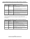
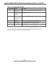
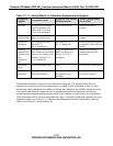
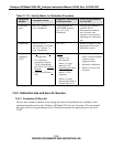
Table 7-7-11: Activity Matrix for Calibration Equipment and Supplies
Equipment/
Supplies
Acceptance Limits
Frequency And Method
Of Measurement
Action If Requirements
Are Not Met
Recorder Compatible with output
signal of analyzer; min
chart width of 150 mm
(6 in) is recommended
Check upon receipt Return equimpent to
supplier
Sample line
and manifold
Constructed of PTFE,
glass, or stainless steel
Check upon receipt Return equipment to
supplier
Calibration
equipment
Meets guide-lines and
Section 2.3.2
(Q. A. Handbook)
See Section 2.3.9
(Q. A. Handbook)
Return equipment/ supplies
to supplier or take corrective
action
Working
standard NO
cylinder gas or
NO
2
permeation
tube
Traceable to NIST-SRM
Meets limits in traceability
protocol for accuracy and
stability. (Section 2.0.7,
Q. A. Handbook)
Analyzed against NIST-
SRM; see protocol in
Section 2.0.7, Q.A.
Handbook
Obtain new working
standard and check for
traceability
Recording
forms
Develop standard forms N/A Revise forms as appropriate
Audit
equipment
Must not be the same as
used for calibration
System must be checked
out against known
standards
Loacte problem and correct
or return to supplier
Calibrations should be carried out at the field monitoring site. The Analyzer should be in
operation for at least several hours (preferably overnight) before calibration so that it is fully
warmed up and its operation has stabilized. During the calibration, the M200A should be in the
CAL mode, and therefore sample the test atmosphere through all components used during
normal ambient sampling and through as much of the ambient air inlet system as is practicable.
If the instrument will be used on more than one range, it should be calibrated separately on each
applicable range, see Section 7.9. Calibration documentation should be maintained with each
analyzer and also in a central backup file.
7-13
PRINTED DOCUMENTS ARE UNCONTROLLED


