Teledyne API Model 200A NO
X
Analyzer Instruction Manual, 02246, Rev. G, DCN 5247
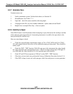
4. Change in span gas concentration.
A.
Zero air or ambient air leaking into span gas line.
B.
Permeation tube or cal gas tank exhaustion.
5.
Leak in NO/NO
x
or AutoZero switching valves.
6.
Loose pneumatic fittings.
9.2.1 AC Power Check
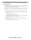
1. Check that power is present at main line power input. Verify that correct voltage and
frequency is present. If unit is set for 240 VAC and is plugged into 115 VAC it will appear as
a no power fault.
2.
Check that the unit is plugged into a good socket. Analyzer must have 3-wire safety
power input.
3.
Check circuit breaker. The circuit breaker is part of the front panel power switch. It is set
each time the instrument power is turned on. If there is an internal short causing a trip, the
switch will automatically return to the OFF position when an attempt is made to turn it on.
9.2.2 Flow Check
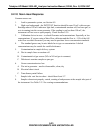
1. Check TEST function RCEL - this is the absolute pressure in the reaction cell.
It should be 5 - 10 in-Hg-A.
2.
Check that pump is running. Check RCEL - TEST function for proper pressure.
3.
Check that the pump tubing is connected to rear of analyzer.
4.
Test that pump is producing vacuum by removing fitting at rear of analyzer and checking
for suction at fitting.
5.
Check for flow at reaction cell.
A.
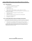
Remove the 1/8" fitting that carries sample (this tube comes from the valve assembly on
the moly converter). Plug the fitting on the reaction cell with your finger and note the
vacuum produced.
B.
Remove the ozone fitting also and compare relative flow rates. Sample should be much
higher (500 cc/min) than ozone (80 cc/min).
C.
Re-connect the sample and ozone lines, then check RCEL TEST function for proper
vacuum reading. Should be 5 - 10"Hg-A.
6.
Check for broken flow or pressure sensor.
7.
Leak check analyzer. See Section 8.9 for leak check procedure.
9-27
PRINTED DOCUMENTS ARE UNCONTROLLED


