


Teledyne API Model 200A NO
X
Analyzer Instruction Manual, 02246, Rev. G, DCN 5247
PSM Diagnostic Procedures
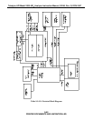
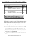
The Linear Power Supply board can be tested by checking the DCPS - TEST function on the
front panel. It should read 2500 mV ± 200 mV. If the value is outside this range, individual
output voltages can be tested on connector P3, see Schematic in the Appendix for pinouts.
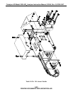
The Switching Power Supply output can be tested by observing the temperature of the PMT cold
block using the PMT TEMP - TEST function. The temperature should be constant 7± 2
C. The
output voltage can be observed on J10 of the Switch Board. It should be 15 VDC ± 0.5.
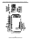
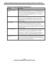
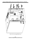
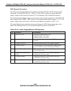
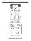
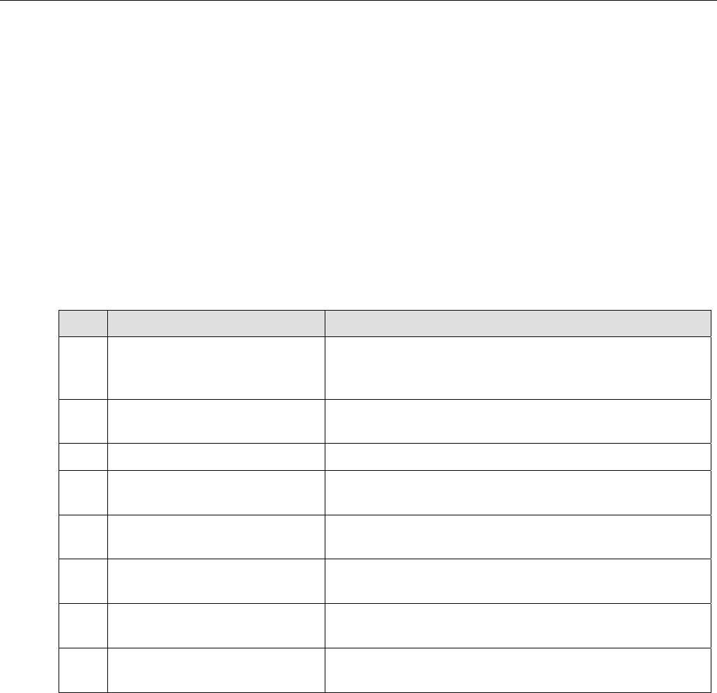
The Switch Board can be tested by observing the diagnostic LEDS along the top edge of the
board. The following Table 9-9-16 describes the typical operation of each LED.
Table 9-9-16: Power Supply Module LED Operation
No. Function Description
1. NO/NO
x
Valve Should switch about every 5 sec.
On(click sound) = NO
x
mode
Off(thud sound) = NO mode
2. Zero/Span Valve Should switch ON when CALZ or CALS button is
pressed.
3. Sample/Cal Valve Should switch ON when CALS button is pressed.
4. AutoZero Valve ON when M200A in AutoZero mode. Happens once
every 6 NO/NO
x
cycles or about once per minute.
5. Ozone Generator Power The ozone generator will be on if it has been more than 30
min since power up.
6. Sample flow control block
heater
Should cycle ON-OFF every 20 sec to 2 min. On
continuously until up to temp.
7. Converter Heater Should cycle ON-OFF every 20 sec to 2 min. On
continuously until up to temp.
8. Reaction Cell Heater Should cycle ON-OFF every 20 sec to 2 min. On
continuously until up to temp.
9-53
PRINTED DOCUMENTS ARE UNCONTROLLED