


Teledyne API Model 200A NO
X
Analyzer Instruction Manual, 02246, Rev. G, DCN 5247
9.3.3.1 ADC/DAC Calibration Procedure
Due to the stability of modern electronics, this procedure should only need to be performed if a
major sub-assembly is exchanged or when the display voltage does not match the input voltage
or current to the V/F card. After completion, a Factory Calibration Procedure should be
performed, see Section 9.1.6.
Before the actual calibration is performed, switches on the V/F card mu
st be correctly set and
jumpers set on the mother board.
Jumper and switch setting changes must be performed with
the instrument power OFF.
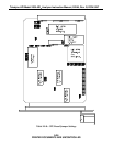
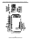
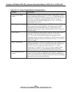
Motherboard Jumpers
The motherboard contains 4 pairs of jumpers JP1 - JP8, one pair for each analog output channel.
Each channel can be configured for either voltage or current output. Use the Table 9-9-10 to
configure the jumpers.
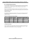
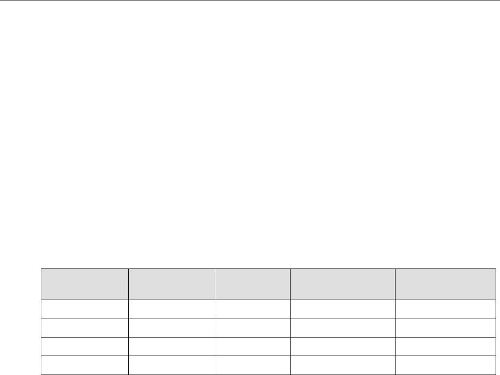
Table 9-9-10: Motherboard Jumper Settings
Analog output
Terminal Pair
Rear panel
Jumper
Pair
Jumper Setting for
Voltage Mode
Jumper Setting
for Current Mode
DAC 0 - NOx 3-4 JP3 - JP4 B-C A-B
DAC 1 - NO 5-6 JP1 - JP2 B-C A-B
DAC 2 - NO2 1-2 JP5 - JP6 B-C A-B
DAC 3 - TEST 7-8 JP7 - JP8 B-C A-B
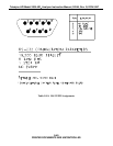
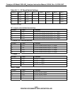
V/F Board Switch Settings
There are 2 different types of current outputs, Non-Isolated (std equipment) and Isolated. Each
requires a different switch setting shown below. If you are operating the instrument in voltage
output mode, the switches should be set to the desired voltage range.
9-43
PRINTED DOCUMENTS ARE UNCONTROLLED