Teledyne API Model 200A NO
X
Analyzer Instruction Manual, 02246, Rev. G, DCN 5247
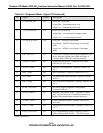
Table 9-4: Diagnostic Mode - Signal I/O (Continued)
No. Signal Control Description
21 ST_POWER_OK YES Status Bit - Power OK
Logic High = Instrument power is on
Logic Low = Instrument power is off
22 ST_SYSTEM_OK YES Status Bit - System OK
Logic High = No instrument warnings present
Logic Low = 1 or more alarms present
23 ST_HIGH_RANGE YES Status Bit - Autorange High Range
Logic High = M200A in high range of autorange
mode
Logic Low = M200A in low range of autorange
mode
24 PMT_SIGNAL NO Current PMT voltage. Same as PMT voltage in TEST
menu. Bi-polar, typically in 0-5000 mV range. A
constant value of 5000 mV indicates offscale.
25 SAMPLE_PRESs NO Sample pressure in mV. Typical sea level value =
4300 mV for 29.9" Hg-A.
26 RCELL_TEMP NO Reaction Cell temperature. Typically 3500 mV for
50 C.
27 BOX_TEMP NO
Box Temperature. Typically 1800 mV for 25 C
28 IZS_TEMP NO IZS permeation tube oven temp. Typically 3500 mV
for 50 C.
29 PMT_TEMP NO PMT cold block temperature. Typically 3600 mV for
10 C.
30 DCPS_VOLTAGE NO DC power supply composite voltage output.
Typically 2500 mV.
31 RCELL_PRESS NO Reaction Cell Pressure in mV. Typically 1270 mV
for 5" Hg-A at sea level. Is an absolute pressure so
higher values means higher absolute pressures.
32 OZONE_FLOW NO Ozone flowmeter voltage. Typically 2000 mV at
80 cc/min.
33 CONV_TEMP NO Molybdenum Converter temp. Typically 3150 mV at
315 C.
34 HVPS_VOLTAGE NO HVPS programming voltage. Output of HVPS is
1000x value present. 700 mV = 700 VDC output.
(table continued)
9-15
PRINTED DOCUMENTS ARE UNCONTROLLED


