


Teledyne API Model 200A NO
X
Analyzer Instruction Manual, 02246, Rev. G, DCN 5247
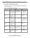
4. Calculate the resulting NO
2
concentrations as follows:
F
]
NO
[*
F
+
]
[NO -
]
[NO =
]
NO
[
T
IMP
2
NO
REMORIGOUT
2
Equation 7-10
Where:
[NO]
ORIG
is the NO concentration before the GPT ozone is turned on, and [NO]
REM
is the NO
remaining after GPT.
5.
Plot the NO
2
concentration output by the instrument on the y-axis against the generated
NO
2
[NO
2
]
OUT
on the x-axis. The plot should be a straight line within the ± 2% linearity
criteria given for the NO
x
and NO channels. If the plot is not linear the most likely cause is
that the converter needs replacing. See Section 7.8.6 on Moly converter efficiency.
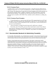
7.8.6 Moly Converter Efficiency
The moly efficiency should be 96 to 102% efficient. If it is outside these limits it should be
replaced. The converter efficiency can be determined from the data collected in 7.8.5.3.
For each NO
2
concentration generated:
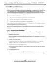
1.
Calculate the concentration of NO
2
converted as:
)]
Equation 7-11
Where:
[NO
x
]
ORIG
is the NO
x
concentration before the GPT ozone is turned on, and [NO
x
]
REM
is the
NO
x
remaining after GPT.
NO
[ -
]
NO
([ -
]
NO
[ =
]
NO
[
REM
x
ORIG
x
OUT
2
CONV
2
2.
Plot the [NO
2
]
CONV
concentration output by the instrument on the y-axis against the
concentration generated [NO
2
]
OUT
on the x-axis. The plot should be a straight line within the
± 2% linearity criteria given for the NO
x
and NO channels.
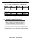
3.
Determine the best straight line fit of the plot either by inspection or least squares. The
slope of the resulting straight line is the moly efficiency. The value should be between .96
and 1.02. If not, the moly needs to be replaced.
4.
If you want the M200A to automatically compensate (Section 7.8.6.1) for converter
efficiency, enter the efficiency value in the front panel by CAL-CONC-MOLY-SET, then
key in the slope from step 3 followed by ENTR. Press EXIT to return to the SAMPLE menu.
7-25
PRINTED DOCUMENTS ARE UNCONTROLLED