


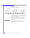
1
1-10
EMC Fibre Channel Disk-Array Processor Enclosure (DPE) Hardware Reference
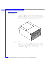
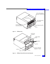
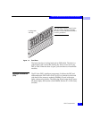
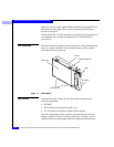
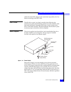
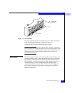
About the Rackmount Disk-Array Processor Enclosure
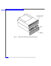
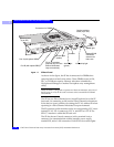
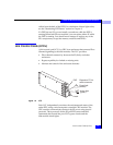
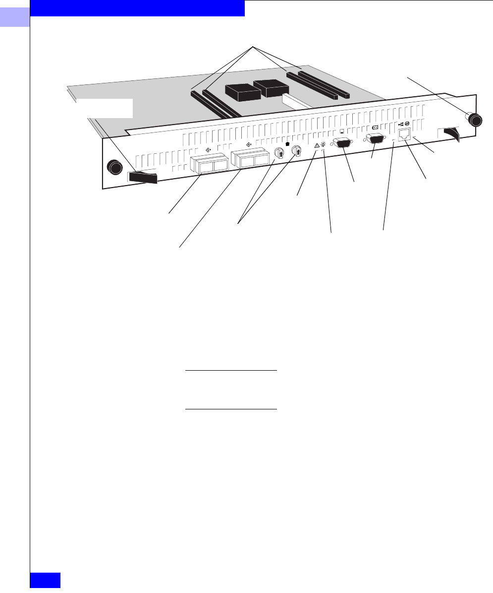
Figure 1-7 SP Back Panel
As shown in the figure, the SP has 4 connectors for DIMMs that
comprise both read and write caches. These DIMMs come in 128-,
256-, or 512-Mbyte capacity. Memory allocation is handled by
Navisphere
® Manager or another Navisphere array management
utility.
When the DPE is configured to operate in a fabric environment, only one of
the SP ports (A or B) can be used to connect to the external Fibre Channel
environment.
The SP has two Fibre Channel ports (A and B) referred to as the SP
front end, for connecting to the external Fibre Channel environment.
It also has two rotary switches for setting the FC-AL address ID when
operating in a Fibre Channel Arbitrated Loop environment.
The SP connects to disk modules and to its corresponding LCC via an
internal FC-AL. SP A connects to LCC A, and SP B to LCC B. The
SP-LCC interface is called the SP back end.
The SP also has an Console connector (with a terminal icon), a
connector for communication with the standby power supply,
marked SPS, and a LAN connection. Each SP has four status lights
Port A (with optical GBIC)
Port B (with optical GBIC)
FC-AL ID switches
(required only for Fibre
Channel Arbitrated
Loop environment)
Check Light
(amber)
Active light
(green)
Network/RJ45
connection
reserved for
future use
SPS
Console
Connectors for DIMMS
Link/activity light
Speed light
Release lever
(2 per SP)
Captive retaining
screw (2 per SP)