


Instruction Manual
748214-V
June 2009
Rosemount Analytical Inc. A Division of Emerson Process Management Preface P-7
Model 951C
CONDENSED STARTUP AND CALIBRATION PROCEDURE
The following summarized instructions on
startup and calibration are intended for opera-
tors already familiar with the analyzer.
For initial startup, refer to detailed instructions
provided in Section 3.
1. Review the Purchase Order from the 951C
Analyzer. Make a note of the Range that
was purchase (Low Range, Mid Range, or
High Range).
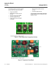
2. Set Range switch on the Signal Conditioning
Board to position 4, 250ppm, 500ppm, or
2500 ppm (see Figure 3-2, page 3-2).
3. On the Signal Conditioning Board, Verify that
Hi/Mid/Lo Range Configuration Jumpers are
installed for the Range that was purchase
(Figure 3-7, page 3-3)
4. Apply power to the analyzer. The analyzer
will now require approximately one to two
hours for temperature equilibrium before be-
ing ready for calibration.
5. Verify that the pressure regulator on the cyl-
inder of zero gas (nitrogen or air) or sample
gas is set for supply pressure of 10 to 17
psig.
6. Verify that the pressure regulator on the cyl-
inder of air (ozonator supply) is set for supply
pressure of 20 to 25 psig.
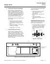
7. Establish correct pressure of sample gas:
a. Supply sample gas to rear-panel SAM-
PLE inlet at 10 to 17 psig (normally 15
psig).
b. Adjust SAMPLE Back Pressure Regula-
tor so that SAMPLE Pressure Gauge in-
dicates the value appropriate to the
desired operating range (normal operat-
ing pressure is 3 to 5 psig). Using the
Mid range setting, set the sample pres-
sure regulator to 2.5 psig See Figure
3-1.
8. Establish correct pressure of zero gas:
a. Supply zero gas to rear panel SAM-
PLE inlet and set to 15 psig.
b. Note reading on SAMPLE Pressure
Gauge. It should be the same as in
Step 6b. If not, adjust output pres-
sure regulator on the zero gas cylin-
der as required.
7. Establish correct pressure of upscale
standard gas:
a. Supply upscale standard gas to rear
panel SAMPLE inlet.
b. Note reading on SAMPLE Pressure
Gauge. It should be the same as in
Step 7b. If not, adjust output regula-
tor on cylinder of upscale standard
gas as required.
NOTE
Supply pressure for sample, upscale
standard gas and zero air must be the
same. If not, the readout will be in error.
8. Zero Calibration:
a. Set PPM RANGE Switch (Figure
3-6, page 3-3) for range to be used
for sample analysis. Set the front
panel RANGE1 Control at normal
operating setting, if known, or at
about middle or the range if normal
setting is not known.
b. Supply zero gas to rear panel SAM-
PLE inlet.
c. Adjust front panel ZERO Control for
reading of zero on meter or recorder.
9. Upscale Calibration:
a. Set PPM RANGE Switch (Figure
3-6, page 3-3) at setting appropriate
to the particular span gas.