


Instruction Manual
748214-V
June 2009
3-6 Operation Rosemount Analytical Inc. A Division of Emerson Process Management
Model 951C
3-3 CALIBRATION
a. Zero Calibration
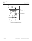
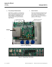
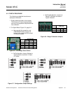
1. On the Signal Board (Figure 3-2,
page 3-2), set PPM RANGE Switch
(Figure 3-6, page 3-3) for the same
range that will be used during sample
analysis. Set front panel RANGE1
Control at about mid-range.
2. Supply zero gas to rear panel SAM-
PLE inlet.
3. Using the MID Range set the sample
pressure regulator to 2.5 psig. Using
the Lo or Hi ranges, set the sample
pressure to 4.0 psig
4. After a stable reading is reached, ad-
just the zero by inserting a screw-
driver in the ZERO slot on the front
panel of the analyzer and turning until
zero reading is obtained.
b. Upscale Calibration
1. On the Signal Board (Figure 3-2,
page 3-2) set Upscale Calibration
PPM RANGE Switch (Figure 3-6,
page 3-3) to the position appropriate
to the particular span gas.
2. Supply upscale standard gas of accu-
rately known NO
X
content to rear
panel SAMPLE inlet.
3. Using the MID Range set the sample
pressure regulator to 2.5 psig. Using
the Lo or Hi ranges, set the sample
pressure to 4.0 psig
4. Adjust front panel RANGE1 Control
so that reading on display or recorder
is equal to the known parts-per-million
concentration of NO
X
in the span gas.
If the correct reading is not initially at-
tainable by adjustment of the front
panel RANGE1 Control, make the
electronic adjustment in Step 5.
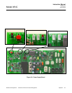
5. If necessary, increase sensitivity by
raising photomultiplier voltage. Adjust
R30 on the Power Supply Board
(Figure 3-9) clockwise to increase
(negative) the photomultiplier high
voltage and sensitivity. This will inter-
act with zero. Repeat Zero Calibra-
tion and Upscale Calibration (through
step 3).
6. If necessary increase the upscale
readings on the LCD display by ad-
justing potentiometer R43 until the
display shows the correct span gas
readings. Now, adjust R 25 so that
reading on display and the recorder is
equal to the known parts-per-million
concentration of NO
X
in the span gas.
3-4 ROUTINE OPERATION
After calibrating analyzer per Section 3-3,
supply sample to SAMPLE inlet. Set PPM
RANGE Switch (Figure 3-6, page 3-3) in ap-
propriate position. The instrument will now
continuously analyze the sample stream.
The Model 951C is designed for continuous
operation. Normally, it is never turned off ex-
cept for servicing or for a prolonged shut-
down.
NOTE
During periods of shutdown, turn off the
ozone lamp by shutting off the input air
source.
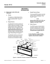
3-5 CONVERTER TEMPERATURE
ADJUSTMENT PROCEDURE
Once the appropriate high voltage and elec-
tronic gain have been selected such that the
named calibration gas value is indicated by
the Model 951C, the instrument is ready for
adjustment of the converter temperature.
The vitreous carbon converter used in this
analyzer has a low surface area which gradu-
ally increases during high temperature opera-
tion of the converter material.