


Instruction Manual
748214-V
June 2009
4-2 Theory Rosemount Analytical Inc. A Division of Emerson Process Management
Model 951C
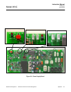
4-3 SIGNAL CONDITIONING AND DISPLAY
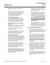
A block diagram of the signal-processing elec-
tronics is shown in Figure 4-1, page 4-3.
The signal conditioning and display board pro-
vides the following functions:
• Signal conditioning circuit consist-
ing of U14
• An analog to digital converter U15.
• Display device U15
• Range Control circuits U9 and U12
• Post signal amplifier and output
amplifier circuit U5
• Display/Backlight blink control U5
and U6
• Range conditions.
• Remote Control Circuits
All of the above functions are on a single board
located at the front of the instrument. Certain
control requirements (ie) range calibration and
zero offset adjustment are available as screw-
driver adjustments via the front panel. A digital
liquid crystal display is mounted on the rear side
of the board for data display purposes as are
control potentiometers.
a. Circuit Functions
Signal conditioning amplifiers
Boards assembly 6A00326G01/02 is a high
input impedance electrometer amplifier
board.
Current output from the detector unit is con-
verted to voltage by the electrometer ampli-
fier and then further amplified by post
amplifier.
The electrometer amplifier gain may be re-
duced by a factor of 10 by shorting JP1 and
by shorting pins 1 and 2 on P1 with the in-
cluded jumpers, this is used for higher
range selection (ie) 100 to 2500 ppm
NOx.
Gain Amplifier U14
The precision amplifier U14 allows 2 se-
lectable gains, on for 10, 100, and 1000
spans and the other for 25, 250, and
2500 spans.
Intermediate gain ranges as required by
the 951C Lo Range: 10, 25, 100, 250
ppm NOx, Mid Range: 20, 50, 200, 500
ppm NOx or Hi Range 100, 250, 1000,
2500 ppm NOx are obtained by interpo-
lating between the requisite ranges us-
ing Boolean Logic and Analog
Switches.
Range 1 and Range 2 selection
The signal output of U14 is adjusted at
the front panel for instrument calibration
purposes. Any second range may be
chosen by placing a jumper on JP1,
JP2, JP3, or JP4. When the pro-
grammed range is selected, the K2 re-
lay toggles and allowing that range to
be calibrated. Note! If no jumper is pre-
sent only range 1 may be calibrated
Post Amplifiers U5
The conditioned signal from U14 and
the range calibration potentiometers
R101 and R102 are provided to U5.
This amplifier has switch controlled feed
back resistors that permit gain selec-
tions of any range, as determined by
the range switch and associated logic.
An Adjustment potentiometer R25 al-
lows a small correction for inter range
calibration purposes.
The output of U14 is provided to the
Analog to Digital converter for digitiza-
tion and display purposes. Potentiome-
ter R43 allows adjustment of the signal
to the ADC allowing concordance of dis-
play and recorder signals if required.
Normally the ADC should be correctly
calibrated during the factory test proce-
dure and should not require further ad-
justment. Potentiometer R25 allows