


Instruction Manual
748214-V
June 2009
Rosemount Analytical Inc. A Division of Emerson Process Management Operation 3-1
Model 951C
Converter
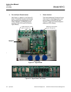
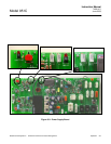
Temp Check
(S4)
Range Select
Switch (SW1)
SIGNAL BOARD
(See Figure 3-2)
Ozone Indicator
Lamp
(Signal Board DS2)
Range1 Control
(Signal Board R101)
Zero Control
(Signal Board R100)
Display
(Signal Board DS1)
ADC Adj
(R43)
0-5VDC Adj.
(R25)
TP1
TP2
Current Output
Span (R20)
Current Output
Zero (R23)
Convertor
Heater
(R9)
PMT
High Voltage
(R30)
Voltage Select
(S2)
Voltage Select
(S1)
Voltage Select
(S3)
CASE HEATER TEMPERAT
URE CONTROL ASSEMBLY
(See Figure 6-4)
TEMPERATURE CONTROL BOARD (See Figure 2-2)
Voltage Select
(S3)
SAMPLE PRESSURE
GAUGE
SAMPLE PRESSURE
REGULATOR
(Adjustment Knob)
POWER SUPPLY BOARD
(See Figure 3-3)
Range2 Control
(Signal Board R102)
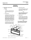
SECTION 3
OPERATION
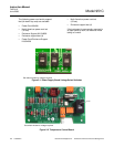
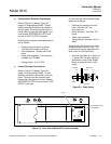
3-1 FRONT PANEL INDICATORS AND
CONTROLS
a. Display
The display is a 4-digit liquid crystal de-
vice which always displays NO
X
concen-
tration in parts-per-million. Figure 3-1
below.
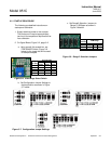
b. Range Selection
The Model 951C has twelve customer se-
lectable ranges, four LO ranges (10 ppm,
25 ppm, 100 ppm and 250 ppm), four MID
ranges (20 ppm, 50 ppm, 200 ppm and
500 ppm), and four HI ranges (100 ppm,
250 ppm 1000 ppm and 2500 ppm). The
range is selected by positioning the PPM
RANGE Switch (SW1) and the five con-
figuration jumpers on the Signal Board to
the desired range controlling the recorder
output. Refer to Figure 3-2, page 3-2.
The Backlight will blink for values 10% in
excess of the range maximum. Moving
the switch to the right selects a higher
fullscale value and restores the display.
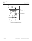
c. Sample Pressure Gauge
The internal SAMPLE pressure (nominally
4 psig, 28 kPa) is adjusted by rotation of
the Sample Pressure Regulator. See
Figure 3-1 below.
NOTE
Using the MID ranges (20, 50, 200, and
500 ppm), set the sample pressure
regulator to 2.5 psig, 17.5 kPa
d. Ozone Pressure
The OZONE pressure is determined by
the pressure regulator of the air supply
cylinder. A nominal pressure of 20 to 25
psig (138 to 172 kPa) is recommended.
Proper operation is indicated when the
front panel OZONE indicator lamp is lit.
NOTE
If ozone lamp does not light, increase
pressure slightly by adjusting pressure
regulator control on the air cylinder.
Figure 3-1. Model 951C Controls, Indicators and Adjustments