


Instruction Manual
748214-V
June 2009
Rosemount Analytical Inc. A Division of Emerson Process Management Installation 2-3
Model 951C
EXHAUST
AIR
IN
20 PSI (138 kPa)
NOMINAL
RECORDER
OUTPUT
POWER
+ -
G
+ -
CUR
OUTPUT
VOLT
OUTPUT
L1/HOT
L2/NEUT
GND
SAMPLE
IN
10 PSI - 17 PSI
(70 kPa - 120 kPa)
FUSE
RANGE 1
RANGE 2
RANGE 3
RANGE 4
RTN
RTN
+24 VDC IN
+24 VDC IN
CHS
GND
CHS
GND
See Figure 2-5 for
connections
Fuse
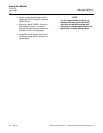
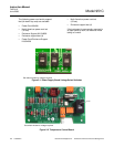
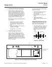
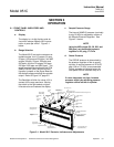
b. Potentiometric Recorder Connections
Refer to Figure 2-3 (below), Figure 2-5
(page 2-4) and drawing 654063. Potenti-
ometric recorder connections are made on
the rear panel. Route the potentiometric re-
corder cable through the cable gland in the
hole labeled RECORDER OUTPUT and
connect to VOLT OUTPUT terminals.
Potentiometric recorder cable specifications
are as follows:
•
Distance from recorder to analyzer:
1000 feet (305 meters) maximum
•
Input impedance: Greater than 2000
ohms
•
Cable (user supplied): Two-conductor,
shielded, min. 20 AWG
•
Voltage output: 0 to +5 VDC
c. Current Recorder Connections
Refer to Figure 2-3 (below), Figure 2-5
(page 2-4) and drawing 654063. Current
recorder connections are made on the rear
panel. Route the current recorder cable
through the cable gland in the hole labeled
RECORDER OUTPUT and connect to CUR
OUTPUT terminals
Current recorder interconnection cable
specs are as follows:
•
Distance the recorder from ana-
lyzer: 3000 feet (915 me-
ters).maximum
•
Load resistance: Less than 700
Ohms.
•
Cable (user supplied):
Two-conductor, shielded, min. 20
AWG
As supplied by the factory, the current
output produces a zero of 4 mA. The
current output may be adjusted to pro-
duce a zero of 0 mA as follows:
1. Zero the instrument as in Section 3-
4. Adjust R23, the zero-adjust po-
tentiometer on the Power Supply
Board, to produce 0 mA current
output.
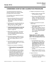
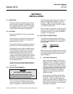
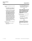
Figure 2-3. Cable Gland
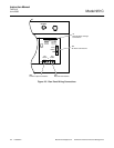
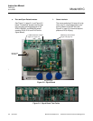
Figure 2-4. Rear View of Model 951C (cover removed)
Case Wall
Cable
Nut Gland Nut
INTERIOR EXTERIOR