


Instruction Manual
748214-V
June 2009
ii Contents Rosemount Analytical Inc. A Division of Emerson Process Management
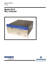
Model 951C
TABLE OF CONTENTS
PREFACE...........................................................................................................................................P-1
Definitions ...........................................................................................................................................P-1
Safety Summary .................................................................................................................................P-2
General Precautions For Handling And Storing High Pressure Gas Cylinders .................................P-5
Documentation....................................................................................................................................P-6
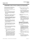
Condensed Startup And Calibration Procedure .................................................................................P-7
1.0 DESCRIPTION AND SPECIFICATIONS ..............................................................................1-1
1-1 Overview................................................................................................................................1-1
1-2 Typical Applications...............................................................................................................1-1
1-3 Specifications.........................................................................................................................1-2
2.0 INSTALLATION ....................................................................................................................2-3
2-1 Unpacking..............................................................................................................................2-3
2-2 location ..................................................................................................................................2-3
1-3 voltage requirements .............................................................................................................2-3
1-4 Electrical Connections ...........................................................................................................2-3
a. Line Power Connections .................................................................................................2-3
b. Potentiometric Recorder Connections ............................................................................2-3
c. Current Recorder Connections .......................................................................................2-3
1-5 Gas Requirements.................................................................................................................2-5
a. Air (U.S.P. Breathing Grade) ..........................................................................................2-5
b. Span Gas ........................................................................................................................2-5
1-6 Sample Requirements ...........................................................................................................2-5
1-7 Gas Connections ...................................................................................................................2-5
1-8 Leak Test...............................................................................................................................2-6
3.0 OPERATION .........................................................................................................................3-1
3-1 Front Panel Indicators and Controls......................................................................................3-1
a. Display ............................................................................................................................3-1
b. Range Selection..............................................................................................................3-1
c. Sample Pressure Gauge.................................................................................................3-1
d. Ozone Pressure ..............................................................................................................3-1
e. Zero and Span Potentiometers .......................................................................................3-3
f. Ozone Interlock ...............................................................................................................3-3
3-2 Startup Procedure .................................................................................................................3-3
3-3 Calibration..............................................................................................................................3-6
a. Zero Calibration...............................................................................................................3-6
b. Upscale Calibration .........................................................................................................3-6
3-4 Routine Operation .................................................................................................................3-6
3-5 Converter Temperature Adjustment Procedure ....................................................................3-6
3-6 Measurement of Converter Efficiency ...................................................................................3-9
3-7 Recommended Calibration Frequency..................................................................................3-9
4.0 THEORY................................................................................................................................4-1