


Instruction Manual
748214-V
June 2009
5-2 Routine Servicing Rosemount Analytical Inc. A Division of Emerson Process Management
Model 951C
c. Ozone Output
WARNING
TOXIC GAS HAZARD
Use extreme caution in troubleshooting
the ozone generator. Ozone is toxic.
To check for adequate output from the
ozone lamp, a convenient technique is to
calibrate the analyzer on a high level NO
standard such as 250 ppm NO at the
nominal 4.0 psi internal sample pressure
setpoint, and note the reading. The sam-
ple pressure setpoint is then sequentially
set to pressures of 3.0, 2.0, and 1.0 psi
after a stable span gas reading has ob-
tained at the higher pressure setpoint.
The span gas value will change as the
pressure is changed. The difference in
span gas value between two successive
sample pressure levels should be ap-
proximately the same for the 4.0 to 3.0,
3.0 to 2.0, and 2.0 to 1.0 pressure steps.
If the size of the span gas value differ-
ence increases as the sample pressure is
lowered, the analyzer output is limited by
the amount of ozone production from the
lamp and the two additional checks
should be made. First, verify that the
sample flow (not including bypass) does
not exceed the nominal 60 to 80 cc/min,
at 4.0 psi internal sample pressure. Sec-
ond, substitute another lamp to see if the
ozone output is increased.
If no other ozone lamp is available, the
analyzer sample input pressure may be
reduced to the pressure where the ozone
limitation is not present. If the lamp output
is low and the sample pressure is reduced
to restore operation to the condition
where ozone limitation is not occurring,
some degradation in analyzer response
time characteristics may occur.
d. Background Current
With zero air supplied to rear panel SAM-
PLE inlet, excessive background current
is evidenced by the inability to obtain zero
display reading with adjustment of the
ZERO Control. If this cannot be accom-
plished, the cause must be found and cor-
rected. The fault may be in either the
electronic circuitry or the sample flow sys-
tem.
First, establish proper performance of the
electronic circuitry. Turn on analyzer
power. Verify that ZERO Control and am-
plifier are functioning properly. Then,
check for excessive photomultiplier dark
current and/or contamination of the reac-
tion chamber or sample flow system as
follows:
•
Excessive Photomultiplier Dark Cur-
rent
To check, shut off all flow to the
ozone generator. Turn off ozone
generator. Supply cylinder air to rear
panel SAMPLE inlet. Note response
on display or recorder. If back-
ground is still excessive, possible
causes are:
leakage of ambient light to photomul-
tiplier tube
defective photomultiplier tube
electrical leakage in socket assembly
•
Contamination of Reaction Chamber
or Sample Flow System.
See Section 5-4a, page 5-7.
5-2 SERVICING FLOW SYSTEM
To facilitate servicing and testing, the Model
951C has front drawer access.
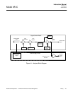
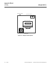
Drawing 654090 shows flow system details,
including fittings, thread specifications and
connecting tubing.
a. Cleaning Sample Capillary
If clogging of sample capillary is sus-
pected, measure flow rate as described
below.