


Instruction Manual
748214-V
June 2009
Rosemount Analytical Inc. A Division of Emerson Process Management Operation 3-7
Model 951C
Initially, the temperature of the peak of the
converter efficiency starts at a relatively high
value because significant heat must be sup-
plied to make the converter active enough to
reduce the input nitrogen dioxide to nitric ox-
ide at the required 95% level. During the op-
eration of the analyzer, the temperature of the
peak will fall as the surface area of the con-
verter is increased and less external energy is
required to cause adequate conversion.
In extreme cases, where converter re-profiling
has not been conducted, the converter is so
active that it not only reduces nitrogen dioxide
to nitric oxide, but it reduces the nitric oxide
produced to nitrogen, which is not detected by
the chemiluminescence reaction. The remedy
in this case is to adjust the converter tempera-
ture to a lower value to improve the converter
efficiency.
It is important that the converter temperature
be periodically profiled to assure that it is run-
ning at its peak efficiency. An interval of one
week is recommended. The nominal range of
operational temperatures for the converter is
275°C to 400°C (527°F to 750°F). The operat-
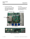
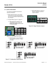
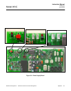
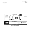
ing temperature of the converter may be con-
veniently checked on the Power Supply Board
(Figure 3-9, page 3-5) by momentarily de-
pressing switch CONV TEMP CHECK (S4)
while monitoring the resistance across termi-
nals TP1 and TP2.
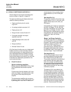
Table 3-1 allows for conversion of the ob-
served resistance to the operating tempera-
ture for the converter.
Follow this procedure to optimize the operat-
ing temperature of the converter:
1. Power instrument and allow it to stabilize
at operating temperature (one to two
hours). Measure the operating tempera-
ture of the converter by the technique de-
scribed above. Note the value for future
reference.
2. Admit a calibration gas of known (NO
2
)
concentration into the analyzer and note
the concentration value determined when
the full response has been achieved.
3. Refer to Power Supply Board Figure 3-9,
page 3-5. Turn the converter temperature
adjust potentiometer (R9 CONV HTR)
one turn counterclockwise from the set-
ting established at the factory, and allow
fifteen minutes for operation at the new
lower temperature setpoint. Recheck the
response and note the value for later use.
4. Increase the temperature of the converter
by rotating the converter temperature ad-
just potentiometer (R9 CONV HTR) one
quarter turn clockwise, wait fifteen min-
utes for thermal equilibrium and then re-
measure the NO
2
calibration gas value.
Note its value. Repeat this procedure of
one quarter turn adjustments of the poten-
tiometer, waiting for thermal stability and
determination of the calibration gas value
until either a 95% value is obtained or the
final one quarter turn adjustment gives an
efficiency increase of less than one per-
cent.
5. Decrease the temperature of converter
operation by rotating the converter tem-
perature adjust potentiometer (R9 CONV
HTR) one eighth of a turn counterclock-
wise. This places the converter at a tem-
perature suitable for low ammonia
interference and efficient NO
2
conversion.
Re-measure the indicated converter tem-
perature and compare it to the initially re-
corded value.
TEMPERATURE
(°
°°
°C)
RESISTANCE
(Ohms)
0 400
25 438
100 552
200 704
250 780
300 856
350 932
400 1008
450 1084
Table 3-1. Resistance of Converter Temperature
Sensor vs. Temperature