


Instruction Manual
748214-V
June 2009
5-4 Routine Servicing Rosemount Analytical Inc. A Division of Emerson Process Management
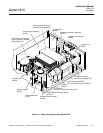
Model 951C
a. Removal
To remove the photomultiplier
tube/reaction chamber assembly from the
analyzer, do the follow:
1. Disconnect power from the analyzer.
2. Release pressure from SAMPLE and
AIR supplies.
3. Unplug the electrical cable from the
Power Supply PC Board.
4. Disconnect the high-voltage cable
and the signal cable from the left side
of the assembly. Note the two mount-
ing screws just below the connectors.
5. Uncouple the sample and ozone cap-
illaries and the exhaust line from the
right side of the assembly. Note the
two mounting screws just below the
fittings.
6. Loosen the screws described in steps
4 and 5 above.
7. Lift the assembly from the analyzer.
8. Replace the assembly by reversing
the order of steps 1 through 7 above.
b. Cleaning Reaction Chamber
NOTE:
Photomultiplier tube will be
permanently damaged if exposed to
ambient light while powered with high
voltage. Photomultiplier tube will
develop temporary electronic noise if
exposed to ambient light with high
voltage OFF. A temporary noisy
condition may be corrected by leaving
instrument on, with high voltage on,
for several hours. The required
recovery time depends on intensity
and duration of the previous exposure.
Noise level on the most sensitive
range usually drops to normal within
24 hours.
If sample gas is properly filtered, the reac-
tion chamber should not require frequent
cleaning. In event of carryover or con-
tamination, however, the chamber should
be disassembled to permit cleaning the
quartz window and the optical filter. The
following procedure is recommended.
1. Cover and shade the Reaction
Chamber/Photomultiplier Assembly
with a dark cloth or other
light-shielding material.
NOTE
Always wear surgical rubber gloves
when handling the reaction chamber to
prevent contamination from handling.
2. Note the orientation of the fittings.
Slowly rotate and withdraw the reac-
tion chamber from the housing. En-
sure that no light strikes the
photomultiplier tube.
3. Unscrew plastic end cap, thus freeing
the quartz window and the red plastic
optical filter. Note the sequence in
which these are assembled.
4. Clean the reaction chamber by the
appropriate one of the following two
methods, standard or alternate. The
standard method is applicable in most
cases. The alternate method is appli-
cable when the instrument has shown
high residual fluorescence. That con-
dition is indicated by high residual
currents on a zero gas and high dif-
ferentials between zero gas readings
obtained with the ozone lamp on and
off.
Standard Cleaning Procedure
Using a stiff plastic bristle brush, such as
a toothbrush, scrub the Teflon surface
and gas ports of the reaction chamber
with clean distilled water and Alconox* de-
tergent (P/N 634929). Alconox detergent
is included in the shipping kit provided
with the Model 951C NO
X
Analyzer, and
is available from Sargent-Welch Scientific