Instruction Manual
748214-V
June 2009
2-6 Installation Rosemount Analytical Inc. A Division of Emerson Process Management
Model 951C
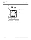
1. Remove plugs and caps from all inlet and
outlet fittings. (See Figure 2-4, page 2-3.)
2. Connect EXHAUST outlet to external vent
via tubing with O.D. of 1/4-inch (6.3 mm) or
larger. Use only stainless steel or Teflon
tubing.
3. Connect external lines from ozonator air
and sample sources to corresponding rear
panel inlet ports. For sample line, stainless
steel tubing is recommended.
4. Adjust regulator on ozonator air cylinder for
output pressure of 20 to 25 psig (138 to 172
kPa). At least 20 psig should be present at
rear of analyzer.
5. Supply sample gas to rear panel SAMPLE
inlet at appropriate pressure: 20 psig (138
kPa). The nominal input pressure is 20 psig
(138 kPa).
2-8 LEAK TEST
The following test is designed for sample
pressure up to 5 psig (35 kPa).
1. Supply air or inert gas such as nitrogen
at 5 psig (35 kPa) to analyzer sample
and air input fittings.
2. Seal off analyzer exhaust fitting with a
tube cap.
3. Use a suitable test liquid such as
SNOOP (P/N 837801) to detect leaks.
Cover all fittings, seals, or possible leak
sources.
4. Check for bubbling or foaming which in-
dicates leakage, and repair as required.
Any leakage must be corrected before
introduction of sample and/or applica-
tion of electrical power.
For positive assurance that system is leak
free, perform one of the tests in Section 5.0.


