


Instruction Manual
748214-V
June 2009
3-2 Operation Rosemount Analytical Inc. A Division of Emerson Process Management
Model 951C
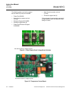
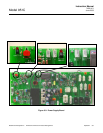
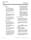
e. Zero and Span Potentiometers
See Figure 3-1 (page 3-1) and Figure 3-2
below. Screwdriver access holes through
the front panel allow adjustments of the
ZERO, RANGE1 and RANGE2 potenti-
ometers (R100, R101 and R102 on the
Signal Board).
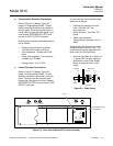
f. Ozone Interlock
The ozone-producing UV lamp will not ig-
nite or stay lit unless adequate air pres-
sure is present at the AIR inlet (see
Figure 2-4, page 2-3). Nominal setpoint
pressure is 20 to 25 psig.
\
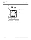
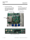
Figure 3-2. Signal Board
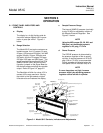
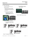
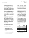
Figure 3-3. Signal Board Test Points
PPM Range Select Switch
(Figure 3-6, page 3-3)
Lo/Mid/Hi Selection Jumpers
(Figure 3-6, page 3-3)
R25 R43
Zero (R100)
Range 2 (R102)
Range 1 (R101)
Electrometer
Assembly