


Instruction Manual
748214-V
June 2009
Rosemount Analytical Inc. A Division of Emerson Process Management Routine Servicing 5-3
Model 951C
1. Turn off instrument power and shut off
all gases.
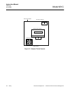
2. Refer to Figure 6-1 (page 6-4) and
Figure 6-2 (page 6-5). Cover and
shade the fittings on the reaction
chamber with a dark cloth or other
light-shielding material. Remove the
fitting associated with the sample cap-
illary and place a cap over the open
fitting to prevent entry of stray light.
NOTE
If the opened fitting is inadvertently
exposed to ambient light, the
instrument will temporarily give a
highly noisy background reading. If so,
this condition may be corrected by
leaving the instrument on, with high
voltage on, for several hours. If high
voltage is on during exposure, the
photomultiplier tube will be destroyed.
3. With instrument power off, supply
suitable test gas (dry nitrogen or air)
to rear-panel SAMPLE inlet.
4. Connect a flowmeter to open end of
sample capillary. Adjust internal
SAMPLE Pressure Regulator to nor-
mal operating setting of 4 psig (28
kPa). Verify that flowmeter indicates
appropriate flow of 60 to 80 cc/min.
5. If flow is correct, restore analyzer to
normal operation.
6. If flow is low, the capillary requires
cleaning or replacement (Proceed
with the step 7 below).
7. Clean capillary with denatured alco-
hol, and purge with dry nitrogen or air
for one minute. Reconnect capillary.
8. With the photomultiplier still covered,
slowly insert the free end of the capil-
lary into the corresponding fitting on
the reaction chamber. Push the capil-
lary in until it touches bottom against
the internal fitting. Then tighten fitting
1/4 turn past finger tight.
NOTE
Do not over-tighten capillary internal
fitting, as over-tightened fittings may
restrict the sample flow.
b. Ozone Restrictor Fitting
With instrument power off, supply suitable
test gas (dry nitrogen or air) to rear panel
AIR inlet. Cover photomultiplier housing
with a dark cloth. At the fittings on the re-
action chamber, disconnect the ozone
tube and place a cap over the open fitting
to prevent entry of ambient light. Connect
a flowmeter to open end of ozone tube.
Adjust the OZONE Pressure Regulator so
that the OZONE Pressure Gauge indi-
cates normal operating pressure of 20 to
25 psig (138 to 172 kPa). Verify that test
flowmeter indicates an appropriate flow of
500 to 600 cc/min for 20 psig.
Subnormal flow indicates clogging in the
flow path that supplies air to the ozone
generator. This path contains a Restrictor
(P/N 655519), consisting of a metal fitting
with internal fritted (metal membrane) re-
strictor to reduce pressure. The fitting is
upstream from the inlet port of the ozone
generator. If the internal restrictor be-
comes plugged, the assembly (P/N
655519) must be replaced as it cannot
normally be cleaned satisfactorily.
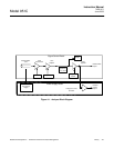
5-3 PHOTOMULTIPLIER TUBE/REACTION
CHAMBER
This assembly consists of the photomultiplier
tube and socket, the thermoelectric cooler,
and the reaction chamber. Refer to Figure 6-1
(page 6-4) for location and details of mount-
ing. Refer to Figure 6-2 (page 6-5) for infor-
mation on the assembly.
The assembly must be removed from the ana-
lyzer in order to clean the reaction chamber or
to replace the photomultiplier tube.