


Instruction Manual
748214-V
June 2009
Rosemount Analytical Inc. A Division of Emerson Process Management Contents i
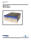
Model 951C
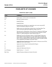
HIGHLIGHTS OF CHANGES
EFFECTIVE JUNE 10, 2009
PAGE SUMMARY
Cover Updated photo, revision number, and release date
P-6 Removed Compliance section
1-1 Added Mid Range
1-2 Added Mid Range
3-1 Added Mid Range, Backlight over range feature, and a note, using the MID
range, set the pressure regulator to 2.5 psig.
3-2 Added a photo of the Signal Board, Added a photo of the Signal Board Test
Points, removed the signal board diagnostic jumpers (Figure 3-4)
3-3 Removed the Hi/Lo Range Select Jumper (Figure 3-5), Updated the PPM Range
selection switch photo and table, removed the decimal point selection jumpers
(Figure 3-7), added Configuration Jumper Settings (Figure 3-7)
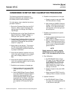
3-6 Added step 3 to the Zero Calibration Section (In the Mid Range Configuration,
Set the Sample Pressure Regulator to 2.5 psig), Added step 3 to the span cali-
bration section (In the Mid Range Configuration, Set the Sample Pressure Regu-
lator to 2.5 psig), Added step 6 to the span calibration section (Use R25 and R43
for fine adjustments to the display and recorder output.)
4-3 Updated the Signal Conditioning and Display section to reflect the current PCB’s,
updated the Circuit function section.
4-5 Updated the Analyzer Signal Conditioning Block Diagram
6-1 Updated the MATRIX
6-3 Updated the Replacement Parts List
List of Drawings Added Drawing 1-1, 1-2, and1-3
Back Cover Updated Company addresses and contact information