


Instruction Manual
748214-V
June 2009
Rosemount Analytical Inc. A Division of Emerson Process Management Installation 2-3
Model 951C
SECTION 2
INSTALLATION
2-1 UNPACKING
Carefully examine the shipping carton and con-
tents for signs of damage. Immediately notify
the shipping carrier if the carton or its contents
are damaged. Retain the carton and packing
material until the instrument is operational.
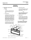
2-2 LOCATION
See drawing 654063 for Outline and Mounting
dimensions.
Install analyzer in a clean area, free from mois-
ture and excessive vibration, at a stable tem-
perature within 4 to 40°C.
The analyzer should be mounted near the sam-
ple source to minimize sample-transport time.
A temperature control system maintains the in-
ternal temperature of analyzer at 50°C (122°F)
to ensure proper operation over an ambient
temperature range of 4°C to 40°C (40°F to
104°F). Temperatures outside these limits ne-
cessitate use of special temperature-controlling
equipment or environmental protection. Also,
the ambient temperature should not change at a
rate exceeding 10°C/hr.
The cylinders of air and span gas should be lo-
cated in an area of constant ambient tempera-
ture (±10°C).
2-3 VOLTAGE REQUIREMENTS
WARNING
ELECTRICAL SHOCK HAZARD
For safety and proper performance this
instrument must be connected to a properly
grounded three-wire source of power.
This instrument was shipped from the factory
set up to operate on 115 VAC, 50/60 Hz electric
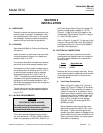
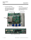
power. For operation on 230 VAC, 50/60 Hz, on
the Power Supply Board (Figure 3-9, page 3-5)
position voltage select switches S1, S2, S3
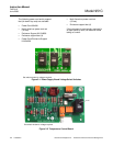
(Figure 2-1, page 2-2) and S3 (located on the
Temperature Control Board (Figure 2-2, page 2-
2) in the 230 VAC position.
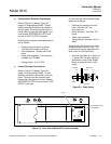
Refer to Figure 2-4, page 2-3. On the rear of the
analyzer, remove the 6.25 A fuse (P/N 902413)
and replace with the 3.15 A fuse (P/N 898587)
provided in the shipping kit.
2-4 ELECTRICAL CONNECTIONS
The power and output (recorder and current)
cable glands are supplied loose in the shipping
kit to allow cable installation to connectors or
terminal strips.
Cable Gland Part No.
Power 899330
Recorder 899329
Remove rear cover to access terminals. Route
each cable through the cable gland and connect
to the appropriate connector or terminal strip,
tighten the gland.
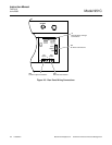
a. Line Power Connections
Refer to Figure 2-3 (page 2-3), Figure 2-4
(page 2-3), Figure 2-5 (page 2-4) and draw-
ing 654063. If this instrument is located on
a bench or table top or is installed in a pro-
tected rack, panel or cabinet, power may be
connected via a 3-wire flexible power cord,
minimum 18 AWG (max. O.D. 0.480", min.
O./D. 0.270"), through the hole labeled
POWER, utilizing connector gland (P/N
899330) provided.
Route the power cable through the cable
gland and connect the leads to TB1 on the
rear panel. Tighten the cable gland ade-
quately to prevent rotation or slippage of the
power cable. Since the rear terminals do not
slide out with the chassis, no excess power
cable slack is necessary.