


Instruction Manual
748214-V
June 2009
Rosemount Analytical Inc. A Division of Emerson Process Management Theory 4-1
Model 951C
SECTION 4
THEORY
4-1 NITRIC OXIDE DETERMINATION BY
CHEMILUMINESCENCE METHOD
The chemiluminescence method for detection of
nitric oxide (NO) is based on its reaction with
ozone (O
3
) to produce nitrogen dioxide (NO
2
)
and oxygen (O
2
). Some of the NO
2
molecules
thus produced are initially in an electronically
excited state (NO
2
*). These revert immediately
to the ground state, with emission of photons
(essentially red light).
The reactions involved are:
NO + O
3
→ NO
2
* + O
2
NO
2
* → NO
2
+ Red Light
As NO and O
3
mix in the reaction chamber, the
intensity of the emitted red light is proportional
to the concentration of NO.
(Any NO
2
initially present in the sample is re-
duced to NO by a heated bed of vitreous carbon
through which the sample is passed before be-
ing routed to the reaction chamber.)
The intensity of the emitted red light is meas-
ured by a photomultiplier tube (PMT), which
produces a current of approximately 3 X 10
-9
amperes per part-per-million of NO in the reac-
tion chamber.
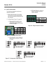
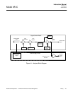
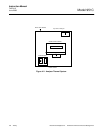
4-2 ANALYZER FLOW SYSTEM
The analyzer flow system is shown in drawing
2-0 and 3-0. Its basic function is to deliver regu-
lated flows of sample, calibration gas, or zero
gas and ozonized air to the reaction chamber.
The discharge from the reaction chamber flows
from the analyzer via the EXHAUST outlet.
a. Flow of Sample, Standard Gas or Zero
Gas to Reaction Chamber
Suitably pressurized sample, standard gas
or zero gas is supplied to the rear panel
SAMPLE inlet.
The flow rate of the selected gas into
the reaction chamber is controlled by a
back pressure regulator inside the ana-
lyzer. It provides an adjustable, con-
trolled pressure on the upstream side,
where gas is supplied to the calibrated,
flow-limiting sample capillary. The regu-
lator is adjusted for appropriate reading
on the internal SAMPLE Pressure
Gauge. For operation at NO and NO
2
levels below 250 ppm, correct setting
on the SAMPLE Pressure Gauge is 4
psig (28 kPa). This results in a flow of
approximately 60 to 80 cc/min to the re-
action chamber.
Excess sample is discharged with the
effluent from the reaction chamber via
the EXHAUST outlet. Bypass flow is set
by the restrictor at 1 L/min (nominal) to
ensure proper functioning of the SAM-
PLE Pressure Regulator and rapid sys-
tem response. Excessive changes, on
the order of 5 psig (35 kPa), in the
pressure of the sample or standard gas
will affect the bypass flow rate and can
affect accuracy.
b. Ozone Generation
Suitably pressurized air from an exter-
nal cylinder is supplied to the rear panel
AIR inlet. The proper pressure setting is
20 to 25 psig (138 to 172 kPa). Within
the ozone generator, a portion of the
oxygen in the air is converted to ozone
by exposure to an ultraviolet lamp. The
reaction is:
From the generator, the ozonized air
flows into the reaction chamber for use
in the chemiluminescence reaction.
UV
3O
2
→ 2O
3