


Instruction Manual
748214-V
June 2009
Rosemount Analytical Inc. A Division of Emerson Process Management Theory 4-3
Model 951C
recorder output adjustment to match dis-
play.
U5 is the recorder output amplifier. The out-
put signal may be trimmed by R25 to pre-
cisely match the recorder calibration. Note
that this adjustment does not affect or
change the instrument display,
Analog to Digital Converter
U15 is a special integrated circuit with a
built in ADC and LCD Drivers. The signal
data is digitized and provided in the correct
format to the liquid crystal display (LCD).
Display/Backlight and over range blink
Circuits
The display circuits comprise of U15, no ad-
justments are required for these functions
The blink or over range display function
uses U5, U6, and U9.
U5 is an analog comparator that senses an
over range condition and turns on U6. U6
sets the blink rate for the Backlight.
Remote Control Circuits
The Model 951C is provided with a fully iso-
lated remote control interface. Optical isola-
tors and a remote 24V power supply ensure
that no direct return path exists between the
users system and the 951C When in the
remote mode of operation.
Relay K1 switches between the internal
range switch control (SW1) and the External
Remote Range Control. When SW1 is on
setting 5 it causes K1 to toggle and a fully
isolated system is achieved.
Optical Isolators U7, U8, U10, and U13 con-
nects via a ribbon cable to the remote con-
nector panel at the rear of the 951C. A ten
terminal barrier strip provides connection for
remote range selection.
Connecting any input terminal 1 thru 4
to ground terminals 9 or10 will select
one of the four ranges.
For remote operation a 24V power sup-
ply should be connected to terminals
5,6 and 7,8, negative or low side is
connected to 5, 6. Positive or high side
to 7,8. For protection purposes the high
side is fused. Note! The local range
switch SW1 must be in the fifth posi-
tion (position Five) to disconnect lo-
cal control and provide the return for
remote control.
For local operation Set the range switch
SW1 between setting 1 thru 4. An ex-
ternal 24V supply is not required. SW1
is located on the top of the signal board.
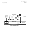
4-4 ANALYZER THERMAL SYSTEM
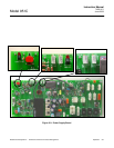
The Analyzer Thermal System is shown in
Figure 4-2, page 4-3. Its basic function is to
provide a stable thermal environment for the
PMT.
The temperature of the PMT must be held
within a half-degree band at approximately
18°C if it is to produce a useful signal for
low concentrations of NO
X
. This is accom-
plished by means of a solid-state cooler
which houses the PMT. The heat which is
radiated from the cooler is carried away by
the Cooler Fan.
The solid-state cooler must work against a
relatively constant load in order to maintain
the temperature of the PMT. This load is
produced by a case heater and exhaust fan
which control the temperature inside the
case within a one-degree band (approxi-
mately 50°C for ambient temperatures from
4°C to 40°C).
The electronics which support the Analyzer
Thermal System and the NO
2
-to-NO Con-
verter are contained on the Power Supply
Board.