


Instruction Manual
748214-V
June 2009
iv Contents Rosemount Analytical Inc. A Division of Emerson Process Management
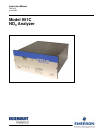
Model 951C
LIST OF ILLUSTRATIONS
Figure 2-1. Power Supply Board Voltage Select Switches .......................................................... 2-2
Figure 2-2. Temperature Control Board ....................................................................................... 2-3
Figure 2-3. Cable Gland .............................................................................................................. 2-3
Figure 2-4. Rear View of Model 951C (cover removed).............................................................. 2-4
Figure 2-5. Rear Panel Wiring Connections................................................................................ 2-4
Figure 3-1. Model 951C Controls, Indicators and Adjustments................................................... 3-2
Figure 3-2. Signal Board.............................................................................................................. 3-3
Figure 3-3. Signal Board Test Points .......................................................................................... 3-3
Figure 3-6. PPM Range Select Switch ........................................................................................ 3-3
Figure 3-7. Configuration Jumper Settings.................................................................................. 3-3
Figure 3-8. Range 2 Selection Jumpers...................................................................................... 3-3
Figure 3-9. Power Supply Board ................................................................................................. 3-5
Figure 4-1. Analyzer Block Diagram............................................................................................ 4-4
Figure 4-2. Analyzer Thermal System......................................................................................... 4-5
Figure 6-1. Major Assemblies of the Model 951C ....................................................................... 6-3
Figure 6-2. Photomultiplier Housing Assembly ............................................................................ 6-4
Figure 6-3. Converter Assembly.................................................................................................. 6-5
Figure 6-4. Case Heater Temperature Control Assembly........................................................... 6-6
LIST OF TABLES
Table 3-1. Resistance of Converter Temperature Sensor vs. Temperature .....................................3-7
LIST OF DRAWINGS
Drawing 1-1 Panel Cutout / Installation Drawing
Drawing 1-2 Flow Diagram, Lo/Mid Range
Drawing 1-3 Flow Diagram, Hi Range