


Instruction Manual
748214-V
June 2009
Rosemount Analytical Inc. A Division of Emerson Process Management Contents iii
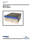
Model 951C
4-1 Nitric Oxide Determination by Chemiluminescence Method .................................................4-1
4-2 Analyzer Flow System ...........................................................................................................4-1
a. Flow of Sample, Standard Gas or Zero Gas to Reaction Chamber ...............................4-1
b. Ozone Generation...........................................................................................................4-1
4-3 Signal Conditioning And Display ...........................................................................................4-2
a. Circuit Functions .............................................................................................................4-2
4-4 Analyzer Thermal System .....................................................................................................4-3
5.0 ROUTINE SERVICING..........................................................................................................5-1
5-1 System Checks and Adjustments..........................................................................................5-1
a. Display Fullscale Span Adjustment.................................................................................5-1
b. Overall Sensitivity............................................................................................................5-1
c. Ozone Output..................................................................................................................5-2
d. Background Current ........................................................................................................5-2
5-2 Servicing Flow System ..........................................................................................................5-2
a. Cleaning Sample Capillary..............................................................................................5-3
b. Ozone Restrictor Fitting ..................................................................................................5-3
5-3 Photomultiplier Tube/Reaction Chamber ..............................................................................5-4
a. Removal ..........................................................................................................................5-4
b. Cleaning Reaction Chamber...........................................................................................5-4
c. Photomultiplier Tube and Housing..................................................................................5-5
d. Replacement of Photomultiplier Tube.............................................................................5-6
5-4 Ozone Generation System ....................................................................................................5-6
a. Lamp/Housing Removal..................................................................................................5-6
b. UV Lamp Replacement ...................................................................................................5-7
c. Power Supply Removal...................................................................................................5-7
5-5 Converter Assembly ..............................................................................................................5-7
5-6 Servicing Electronic Circuitry.................................................................................................5-8
6.0 REPLACEMENT PARTS ......................................................................................................6-1
6-1 Matrix .....................................................................................................................................6-1
6-2 Circuit Board Replacement Policy.........................................................................................6-3
6-3 Replacement Parts ................................................................................................................6-3
a. Common Parts ................................................................................................................6-3
b. Photomultiplier Assembly 654062...................................................................................6-4
c. Converter Assembly 654070...........................................................................................6-5
d. Temperature Control Assembly 654068 .........................................................................6-6
7.0 RETURN OF MATERIAL ......................................................................................................7-2
7-1 return of material ...................................................................................................................7-2
7-2 customer service ...................................................................................................................7-2
7-3 Training..................................................................................................................................7-2
8.0 INDEX....................................................................................................................................8-1