2 - 109
KEYENCE PLC • 2
(KZ-A500)
41
41 KEYENCE PLC • 2
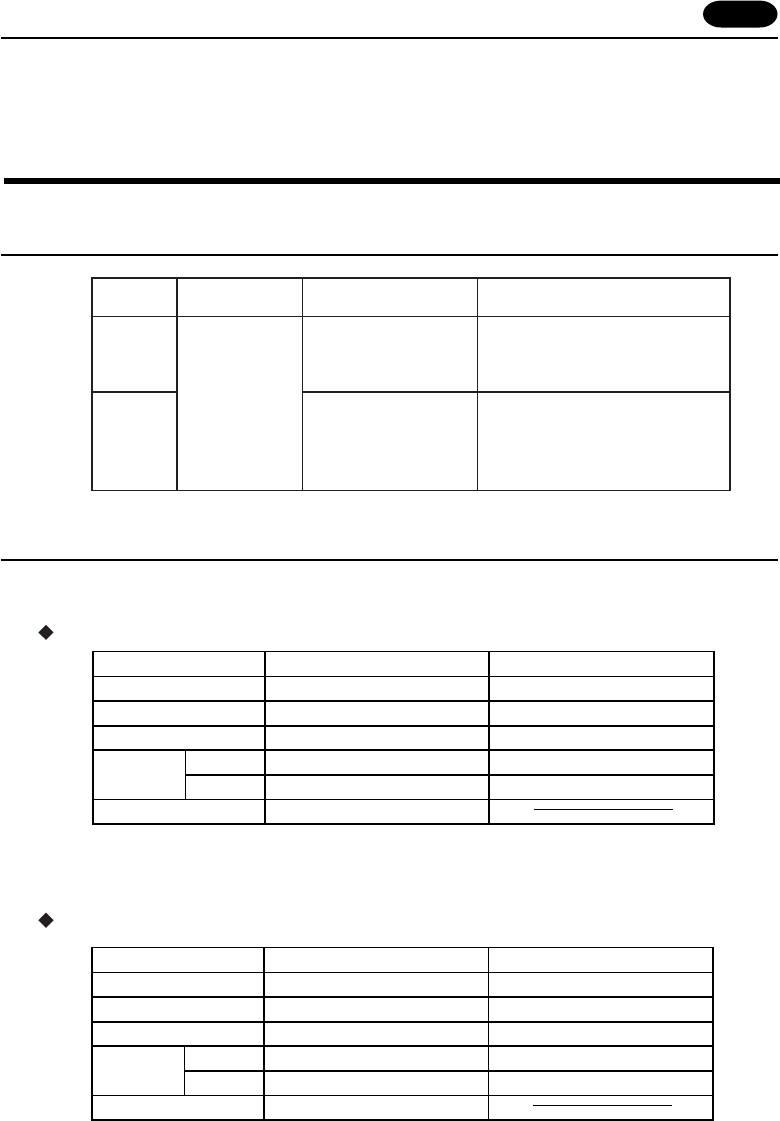
Available PLC
Communication Setting
The recommended communication parameter setting of both PLC and POD is as follows:
CPU modular port of KZ-A500
Link Unit KZ-L10
Set the port with the port setting switch, the terminating resistance with
terminator, and the baud rate/data bit/parity/stop bit with SET B dip switches.
For further information, refer to the communication specifications of KZ-L10.
PLC
Link Unit
Wiring Diagram
KZ-A500
Port 2
RS-232C [Wiring Diagram 3]
RS-422 [Wiring Diagram 4]
KZ-L10
CPU Modular Port
Port 1
RS-232C [Wiring Diagram 2]
Select PLC Type
MITSUBISHI
A series link
KZ-A500
CPU
RS-232C [Wiring Diagram 1]
RS-422 C
able made by KEYENCE [
KZ-C20
]
+ Cable made by Fuji [ UG200C-M ]
9600bps
Odd
8
ON for RS-422
Baud Rate
Parity
Transmission
Code
Data Length
Stop Bit 1
Terminal Resistor
Item Setting of PLC
9600bps
0Port 0
Odd
8
1
*
1
*
1 In case of RS-422, the baud rate is fixed at 9600bps.
Comm. Parameter of POD
19200bps
Even
7
ON for RS-422
Baud Rate
Parity
Transmission
Code
Data Length
Stop Bit 1
Terminal Resistor
Item Setting of PLC
19200bps
0Port 0
Even
7
1
Comm. Parameter of POD


