2 - 27
9 MITSUBISHI PLC • 3
Available Memory
*
1 The unit number is required in addition to the memory type and the address.
Convert a byte address into a word address to enter the data if the memory device of link unit
is byte address.
Set the memory to the extent of the memory range of each PLC model.
Use TYPE number to assign indirect memory for macro programs.
PLC
D-sub 25pin (Male: )
FG
TXD
RXD
RTS
SG
1
2
3
4
7
TXD
DTR
SG
RXD
1
2
5
3
POD (CN1)
*
Use twist shielded cables.
Minimum DIN 6pin (Male: )
Wiring
The following is a diagram to show the wiring of the cable which connects POD to PLC.
RS-232C
Wiring Diagram 1 (connection of the UG00C-Q)
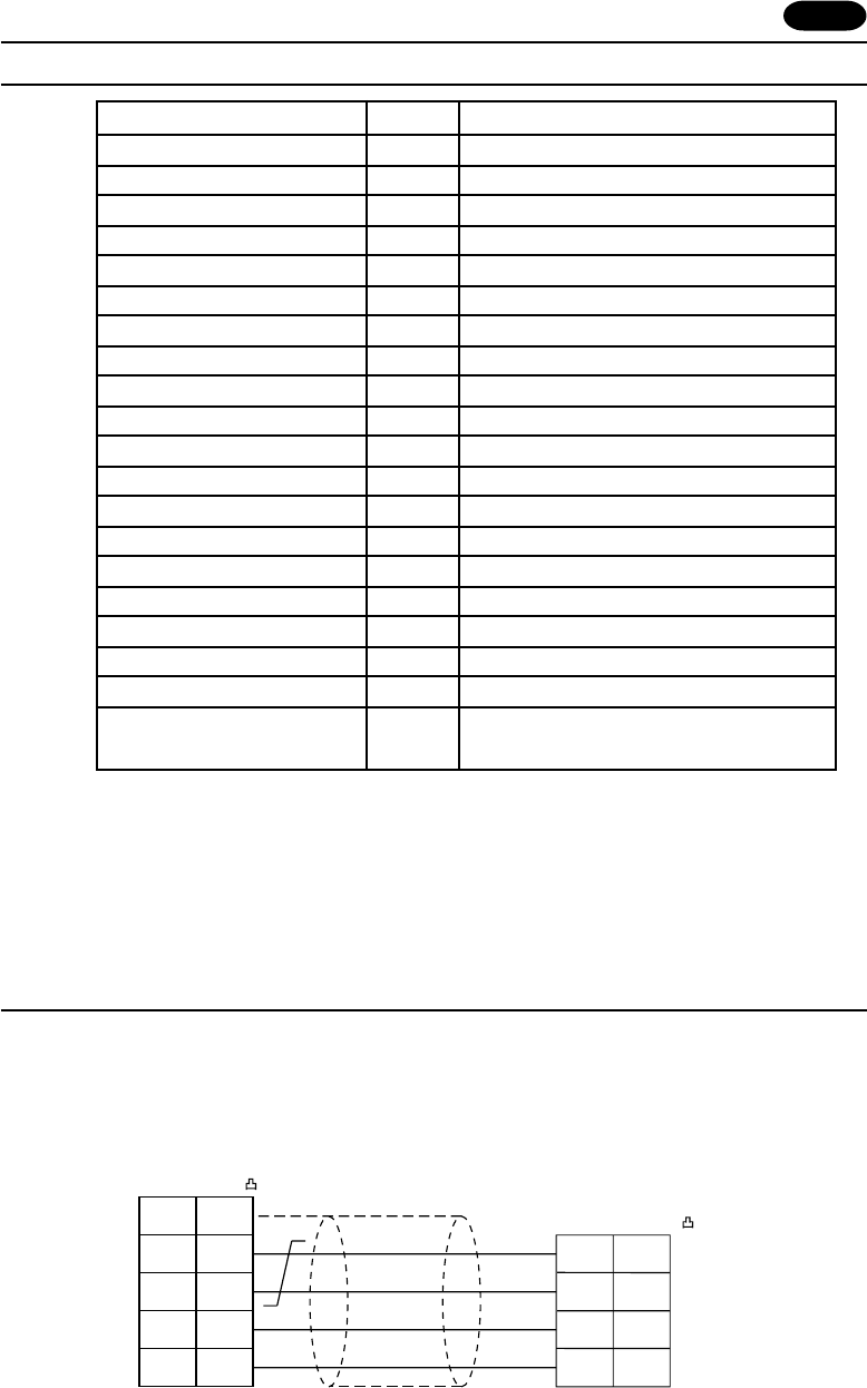
Memory TYPE Remarks
D(data register) 0
W (link register) 1
R (file register) 2
TN (timer/current value) 3
CN (counter/current value) 4
SPU (special unit) 5 Unit No.
*
1
M(internal relay) 6
L (latch relay) 7
B (link relay) 8
X (input relay) 9
Y(output relay) 10
TS (timer/contact) 11
TC (timer/coil) 12
CS (counter/contact) 13
CC (counter/coil) 14
SD (special register) 16 only in Q mode
SM (special relay) 17 only in Q mode
SB (special link relay) 18 only in Q mode
SW (special link register) 19 only in Q mode
ZR 20 only in Q mode
(file register [continuous access])


