Color Change
312779E 107
F
IG
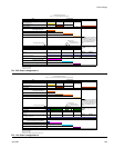
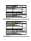
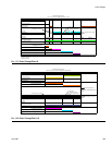
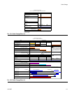
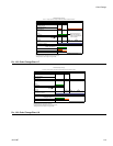
. 113: Color Change Chart 5
Valve Time-Sequence
Dump A
Dump B
Color Change Solvent
Catalyst Change Solvent
Color Change A A
Catalyst Change B B
P0 P1 P2 P3 P4
Catalyst Pur
g
e Time P0->P1
Catalyst Fill Time P1->P2
Air Chop Time
Solvent Chop Time
First Purge (one of these) 3rd Flush Chop Time
Air Purge
Solvent Purge Final Purge (one of these)
3rd Flush Valve
Dispense A AA
Dispense B BB
Gun Trigger(s) by Operator
M0 M1 M2 M3 M4
First Purge Time M0->M1
Chop Time (air/solvent or air/3rd flush) M1->M2
Final Purge Time M2->M3
Mixed Fill Time M3->M4
Notes: Load tables from new recipe
Purge from old recipe
Fill from new recipe
ProMix 2KS Recipe Change
Chart 5: B1 to B2, same A with Dump Valves
CC Pur
g
e/Fill Timers are independent
of Mixed Material Pur
g
e Timers. This
line defines when the Mixed Fill Time
begins. The longer of the two timers
defines when the Mixed Fill Time
begins.
B
B
F
IG
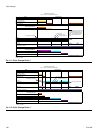
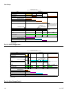
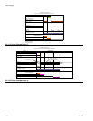
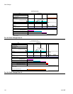
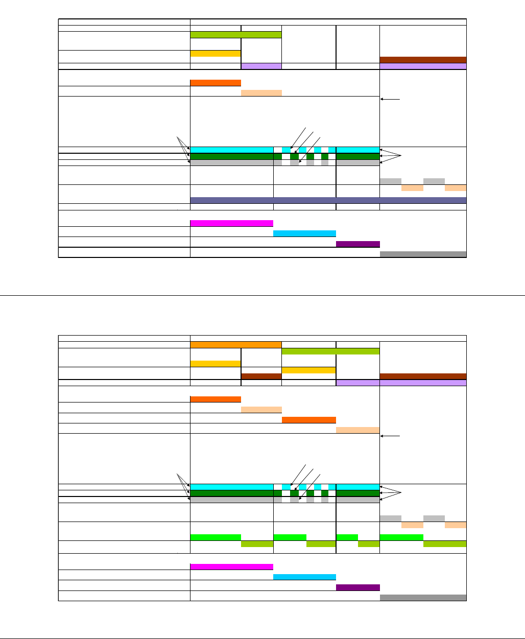
. 114: Color Change Chart 6
Valve Time-Sequence
Dump A
Dump B
Color Change Solvent
Catalyst Change Solvent
Color Change A A
Catalyst Change B B
P0 P1 P2 P3 P4
Color Pur
g
e Time P0->P1
Color Fill Time P1->P2
Catalyst Pur
g
e Time P2->P3
Catalyst Fill Time P3->P4
Air Chop Time
Solvent Chop Time
First Purge (one of these) 3rd Flush Chop Time
Air Purge
Solvent Purge Final Purge (one of these)
3rd Flush Valve
Dispense A AA
Dispense B BB
Gun Flush Box Output #1
Gun Flush Box Output #2
M0 M1 M2 M3 M4
First Pur
g
e Time M0->M1
Chop Time (air/solvent or air/3rd flush) M1->M2
Final Pur
g
e Time M2->M3
Mixed Fill Time M3->M4
Notes: Load tables from new recipe
Purge from old recipe
Fill from new recipe
ProMix 2KS Recipe Change
Chart 6: A1 to A2, B1 to B2 with Dump Valves, 2 GFBs
CC Pur
g
e/Fill Timers are independent
of System Purge Timers. This line
defines when the System Fill Time
begins. The longer of the two timers
defines when the System Fill Time
begins.
A
B
B
A


