


System Configuration and Part Numbers
4 312779E
System Configuration and Part Numbers
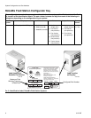
Wall Mount Fluid Station Configurator Key
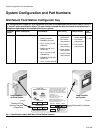
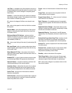
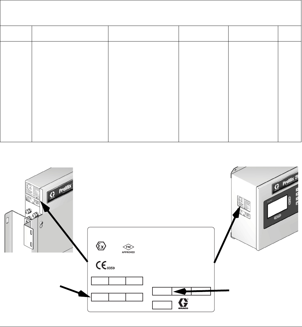
The configured part number for your equipment is printed on the equipment identification labels. See F
IG
. 1
for location of the identification labels. The part number includes one digit from each of the following six
categories, depending on the configuration of your system.
Automatic
System
Control and Display A and B Meter Color Valves Catalyst Valves Flow
Control
A D = EasyKey with LCD Display 0 = No Meters
1 = G3000 (A and B)
2 = G3000HR (A and B)
3 = 1/8 in. Coriolis (A) and
G3000 (B)
4 = G3000 (A) and 1/8 in.
Coriolis (B)
5 = 1/8 in. Coriolis (A) and
G3000HR (B)
6 = G3000HR (A) and 1/8 in.
Coriolis (B)
7 = 1/8 in. Coriolis (A and B)
0 = No Valves
(single color)
1 = Two Valves
(low pressure)
2 = Four Valves
(low pressure)
3 = Seven Valves
(low pressure)
4 = Twelve Valves
(low pressure)
0 = No Valves
(single catalyst)
1 = Two Valves
(low pressure)
2 = Four Valves
(low pressure)
N = No
Y = Yes
F
IG
. 1: Identification Label, Wall Mount Fluid Station Systems
Label Location
on EasyKey
Label Location
on Fluid Station
Maximum Fluid
Working Pressure
is listed here
TI12418aTI12423a
Configured Part Number