


ProMix 2KS Integration Specifics
52 312779E
Digital Inputs
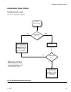
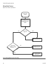
See Automation Flow Charts, pages 55-59.
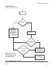
Mix Start: This is a
maintained
input. When High, the
ProMix 2KS will attempt to enter Mix mode. This Mix
Start input should not be attempted unless the
Mix_Ready output is recognized. This ensures that
there are no alarms and that the Mix Start input is appro-
priate.
This input stays High at all times when mixing on
demand is required. When Low, the intent is to stop mix-
ing material and perform a purge or recipe change.
Do not
toggle this input to set the unit to Standby mode
during short work stoppages. The ProMix 2KS will auto-
matically go into Idle mode after 2 minutes of inactivity.
When a Gun Trigger input is seen, the ProMix 2KS will
automatically leave Idle mode and resume mixing mate-
rial where it left off.
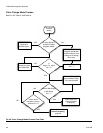
Purge Start: This is a
maintained
input. When recog-
nized by the ProMix 2KS, the Purge Sequence will start,
using the Purge Time from the active recipe. This will
also include the Solvent Fill Time. Proper monitoring of
the Purge/Color Change Output is required to ensure
this function has begun. Once this output is removed,
the system will immediately go to Standby mode.
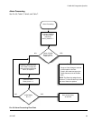
Color Change Start: This is a
momentary
input, 100
msec minimum. When recognized by the ProMix 2KS,
the Color Change sequence will begin, starting at the
Color/Catalyst Dump.
NOTE: If the new recipe has the
same color
as the
active recipe, then the Color/Catalyst Dump and
Color/Catalyst Fill times are skipped and the Color
Change Sequence starts with the Purge. Also, the rec-
ipe bit configuration for the Color Change must be
loaded at least 100 msec before the Color Change Start
input is turned on. The recipe bit configuration
must
remain on while the Color Change Start input is
removed. Graco recommends the recipe bits stay active
and do not change until a new color is required. The
PLC should monitor the Purge/Color Change Output as
well as the Fill Active Output to ensure the process hap-
pens as required. A complete color change without
errors (resulting in a Mix Ready Output state) is a com-
pleted color change.
NOTE: This also applies if using the Modbus Registers
(see the Modbus Map table in manual 312785).
Gun Trigger: When High, this input signals the ProMix
2KS that the gun is actually triggered. It should be sent
every time the gun is triggered. This input provides tim-
ing for alarm functions and also drives the flow control
functions. Without it, no flow control functions will start.
Job Complete:
This is a
momentary
input, 100 msec
minimum. When recognized by the ProMix 2KS, the Job
totals are cleared and a time/date stamp is added for
retrieval.
Remote Stop: Use this input when external equipment
is used to stop the system. Clear any alarms before
using this input. For more information about when this
input is needed, contact your Graco distributor.
Alarm Reset: This is a
momentary
input, 100 msec
minimum. When recognized by the ProMix 2KS it clears
any active alarms and allows the automation to take the
next step.
Common: This is not an input, but the ProMix 2KS
expects to have the COM side of the 24 Vdc supply con-
nected as shown in Table 8. This ensures proper opera-
tion of each input and output.
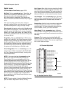
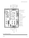
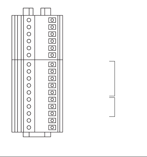
F
IG
. 63: EasyKey Terminal Strips
Pin 1
Pin 1
TI12958a
RS485 Integration A
Flow Rate Analog Common
Alarm Reset
Remote Stop
Digital Common
Gun Trigger
Flow Control Calibrate
Flow Rate Analog In
Potlife Alarm
Digital Common
General Alarm
RS485 Integration B
RS485 Integration Ground
RS485 Network A
RS485 Network B
RS485 Network Ground
I/O Terminal Strip Detail
INPUTS
OUTPUTS