Integrated Flow Control
68 312779E
Fluid and Air Pressure
Requirements
The fluid input pressure to the fluid regulator must be
high enough to provide a 15-20 psi (0.1-0.14 MPa,
1.0-1.4 bar) pressure differential across the regulator at
the highest flow setting.
For example,
if the maximum
flow rate set point is 280 cc/min and 35 psi outlet pres-
sure is required to achieve that flow, the input pressure
must be 50-55 psi.
Required air pressure to the flow control module is
70-100 psi (0.35-0.7 MPa, 3.5-7.0 bar).
NOTE:
• For flow control modules 249849 and 24H989 used
with a 1:1 fluid regulator, the fluid outlet pressure
from the regulator must be between 12-75 psi
(.08-0.5 MPa, 0.84-5.2 bar) for all flow set points.
Flow rate set points with pressures outside this
range are not achievable. There must be at least 12
psi (.08 MPa, 0.84 bar) fluid pressure at the lowest
flow rate.
• If flow control module 24H989 is used with a fluid
regulator at a ratio greater than 1:1, the relationship
of air pressure to fluid outlet pressure is very impor-
tant. The lowest recommended air pressure from
the V/P is 10-12 psi (.07-.08 MPa, 0.70-0.84 bar).
Back pressure will be required to ensure minimal
fluid pressure at the lowest flow rate setpoint.
The turn down ratio of the typical fluid regulator is
approximately 3:1 or 4:1, depending on material type
and viscosity.
For example,
if the lowest flow rate
required is 100 cc/min, the top flow rate achievable may
be 300-400 cc/min.
NOTE: The top flow rate is not the maximum flow rate
range selected.
Flow Control Operation
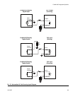
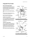
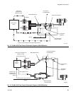
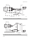
See F
IG
. 73 for module 249849 and F
IG
. 74 for module
24H989. The Flow Control System includes two infor-
mation loops:
•The pressure loop monitors fluid pressure with the
pressure sensor in the module. This allows the sys-
tem to react very quickly to set point changes. The
gun must be triggered during the pressure loop.
•The flow loop monitors fluid flow through flow
meter pulses, ensuring accuracy. The gun must be
triggered during the flow loop.
The Flow Control System creates a data table that tar-
gets a desired flow rate based on the fluid pressure. It
then monitors the flow loop to maintain the flow rate.


