


System Operation
312779E 85
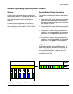
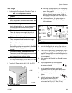
General Operating Cycle, Dynamic Dosing
Overview
Dynamic Dosing provides on-demand proportioning,
eliminating the need for an integrator and therefore min-
imizing undesired material contact. This feature is espe-
cially useful with shear-sensitive and waterborne
materials.
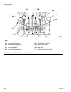
A restrictor injects component B into a continuous
stream of component A. The software controls the dura-
tion and frequency of each injection. See F
IG
. 92 for a
schematic diagram of the process.
Dynamic Dosing System Parameters
The following parameters affect dynamic dosing perfor-
mance:
• Component A Flow: Ensure that the supply pump is
sized to provide sufficient and uninterrupted flow.
Note that component A provides majority of system
flow at higher mix ratios.
• Component B Flow: Ensure that the supply pump is
sized to provide sufficient and uninterrupted flow.
• Component A Pressure: Ensure precise pressure
regulation. It is recommended that the component A
pressure be 5-15% lower than the component B
pressure.
• Component B Pressure: Ensure precise pressure
regulation. It is recommended that the component B
pressure be 5-15% higher than the component A
pressure.
NOTE: When using dynamic dosing it is very important
to maintain a constant, well-regulated fluid supply. To
obtain proper pressure control and minimize pump pul-
sation, install a fluid regulator on the A and B supply
lines upstream of the meters. In systems with color
change, install the regulator downstream of the
color/catalyst valve stack.
F
IG
. 92. Schematic Diagram of Dynamic Dosing Operation
Component A (continuous flow) Proportioned Material
To Static
Mixer
Component B (pulsed injection)