


Setup Mode
44 312779E
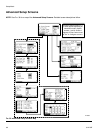
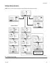
NOTE: Each screen displays the current screen number
and the total number of screens in the group. The total
number of screens in a group and the fields displayed
on each screen may vary depending on selections
made in the System Configuration Screens and
Option Screens.
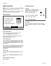
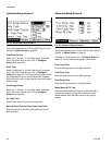
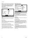
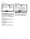
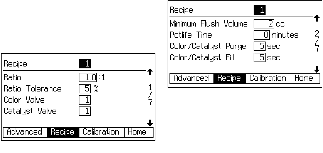
Recipe Setup Screen 1
Ratio
Enter the mix ratio of component A over component B
(0.0:1 to 50:1).
Ratio Tolerance
Enter the ratio tolerance (1 to 99%). This refers to the
percent of acceptable variance that the system will allow
before a ratio alarm occurs.
Component A (Color) Valve (if present)
This field only appears if the system includes a color
change module. Enter the color valve number (1 to 30).
Component B (Catalyst) Valve (if present)
This field only appears if the system includes a color
change module. Enter the catalyst valve number (1 to
4).
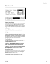
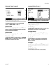
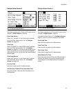
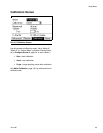
Recipe Setup Screen 2
Minimum Flush Volume
This field only appears if Flush Volume Check is set to
“On” in Option Screen 1 on page 36. Enter the mini-
mum flush volume (0 to 999 cc). Entering 0 disables this
function.
Potlife Time
Enter the potlife time (0 to 999 minutes). Entering 0 dis-
ables this function.
Color/Catalyst Purge
This field only appears if the system includes a color
change module and Flush and Fill Input is set to “Rec-
ipe” in Option Screen 1, page 36. Enter the purge time
(0 to 99 seconds). It refers to the amount of time
required to flush the lines from the color or catalyst mod-
ule to the dose valve or dump valve.
Color/Catalyst Fill
This field only appears if the system includes a color
change module and Flush and Fill Input is set to “Rec-
ipe” in Option Screen 1, page 36. Enter the fill time (0
to 99 seconds). It refers to the time required to fill the
lines from the color or catalyst module to the dose valve
or dump valve.
F
IG
. 50. Recipe Setup Screen 1
F
IG
. 51. Recipe Setup Screen 2