


ProMix 2KS Integration Specifics
312779E 65
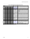
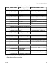
Digital Outputs
1★ J4, Remote I/O Board Digital Output Common/Power
2 J4, Remote I/O Board Purge_CC Active “1” Indicates Purge or Color Change is in
progress
3 J4, Remote I/O Board Mix_Active “1” Indicates Mix is in progress
4 J4, Remote I/O Board Mix_Ready “1” Indicates No Alarms and OK to Mix
5 J4, Remote I/O Board CC_Fill_Active “1” Indicates the Fill Portion of a Color
Change is in progress
6 J4, Remote I/O Board FCalActive “1” Indicates the Flow Control Calibrate rou-
tine is in progress
7 J4, Remote I/O Board Flow_Rate “1” Indicates the Flow Rate Alarm/Warning is
active
8★ J4, Remote I/O Board Digital Output Common/Power
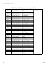
1★ J5, Remote I/O Board Digital Output Common/Power
2 J5, Remote I/O Board Special_1 “1” Indicates the Special_1 Output is on
3 J5, Remote I/O Board Special_2 “1” Indicates the Special_2 Output is on
4 J5, Remote I/O Board Special_3 “1” Indicates the Special_3 Output is on
5 J5, Remote I/O Board Special_4 “1” Indicates the Special_4 Output is on
6★ J5, Remote I/O Board Digital Output Common/Power
6 10 Pin Terminal Block General Alarm Output “1” Indicates the General Alarm Output is on
7◆ 10 Pin Terminal Block Digital Output Common/Power
8 10 Pin Terminal Block Potlife Alarm “1” Indicates the Potlife Alarm Output is on
9 10 Pin Terminal Block Flow Rate Analog In (0-10
VDC)
0 - 10VDC input for Flow Setpoint relative to
flow range set in 2KS Flow Range Screen
10 10 Pin Terminal Block Flow Rate Common to Pin 9 Common side of Flow Setpoint from Terminal
9
Communications
1 6 Pin Terminal Block RS485 Integration A
Communication to External PLC/Controller
2 6 Pin Terminal Block RS485 Integration B
3 6 Pin Terminal Block RS485 Integration
Shield/Ground
4 6 Pin Terminal Block RS485 Network A
Communication to Multiple EasyKeys only5 6 Pin Terminal Block RS485 Network B
6 6 Pin Terminal Block RS485 Network Shield/Ground
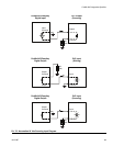
★
Digital outputs tied together on the I/O board (see F
IG
. 64).
◆
Digital outputs tied together on the EasyKey Display Board.
Multiple connection points for convenience.
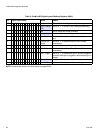
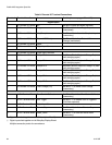
Table 8: Discrete I/O Terminal Connections
Terminal Terminal Location Name Details (also see pages 60 and 61)