


ProMix 2KS Integration Specifics
54 312779E
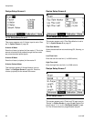
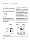
Digital Outputs
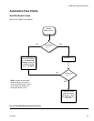
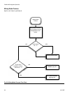
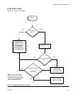
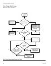
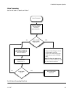
See Automation Flow Charts, pages 55-59.
Purge_CC_Active: This output will remain High during
the manual Purge or Color Change purge sequence.
See the Color Change Charts (F
IG
. 109-F
IG
. 126) for fur-
ther information.
Fill_Active: This output will remain High while the Pro-
Mix 2KS is in the Mixed Material Fill at the end of a typi-
cal color change sequence.
Mix_Active: This output will remain High while the Pro-
Mix 2KS is in Mix mode. There may be alarm outputs
while this output is High; these are typically High/Low
Flow Warnings. Always monitor this output and the
alarm outputs to provide feedback of the actual status of
the ProMix 2KS. (See the Modbus charts in the Graco
Gateway manual 312785.)
Mix_Ready: This output will remain High while there are
no alarms and the ProMix 2KS is ready to go to Mix
mode.
General Alarm: This output will remain High when any
alarm is active. See Table 16 on page 115 for a com-
plete list of alarms.
NOTE: It is important to monitor this output along with
Mix_Active to understand the alarm’s true meaning.
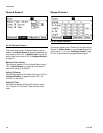
Alarm_Potlife: This output will remain High along with
the Alarm output when the potlife time has been
reached for the active recipe. The Mix_Active output will
drop Low, even if the Mix_Start input is High. This out-
put will remain High until the potlife volume is dispensed
or the ProMix 2KS completes a Purge or a Color
Change. The Alarm Reset input will not stop this output
but will silence the audible alarm on the EasyKey.
NOTE: The Alarm Reset
key will also reset the
audible alarm.
To dispense the potlife volume, the ProMix 2KS
Mix_Start input must be turned Off then back to High to
spray material. At this point, Mix_Active, Alarm, and
Alarm_Potlife outputs will be High until the potlife vol-
ume is sprayed.
Digital Out Supply: This is the supply for the digital out-
puts. It is the same supply for the digital inputs. (See
Common under Digital Inputs, page 52.)
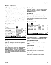
Analog Inputs
Flow Command: This is the positive side of the 0 – 10
Vdc signal. (See Common under Digital Inputs, page
52.) This input corresponds to the Flow Range setting in
Advanced Setup Screen 5, page 41.
For example,
if
the setting is 0 – 300 cc/min, the 0 Vdc analog input is 0
cc/min, therefore the 10 Vdc analog input is 300 cc/min.
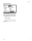
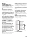
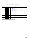
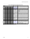
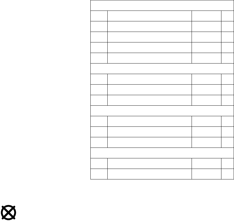
Table 4: Sourcing/Sinking Inputs and Outputs
Inputs (Automation Sourcing)
1 Flow Control Calibration Black +
2 Gun Trigger White +
3 Digital In Common Red -
4 Remote Stop Green +
5 Alarm Reset Brown +
Outputs (Automation Sourcing)
6 Alarm Output Blue +
7 Digital Out Common Orange -
8 Pot Life Yellow +
Outputs (Automation Sinking)
6 Alarm Output Blue -
7 +24 Volts Orange +
8 Pot Life Yellow -
Automation
9 Flow Rate Analog In Purple +
10 Flow Rate Analog Common Gray -