


CONTROLS AND CONNECTIONS
2–3
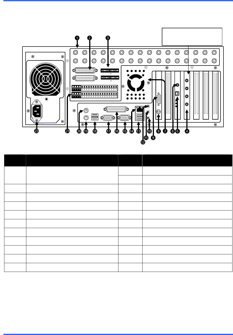
connections displayed may not be available or functional on specific models.
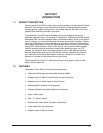
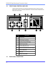
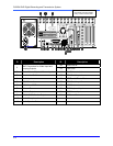
The rear panel of the DVR unit contains virtually all of the connectors you will be using.
Below is a diagram that outlines the location and description of each connector:
32 Channel
ID Description ID Description
12
Audio Line In
1
BNC Connectors for Video Input and
Looping Outputs
13
USB Ports
2
BNC Expansion Ports
14
RJ-45 Network Jack
3
Termination Switches
15
DB-9 Serial Input 1
4
Audio Inputs
16
LPT Parallel Printer Port
5
RS-422 Interface
17
DB-9 Serial Input 2
6
RCA Video OUT
18
USB Ports
7
Exhaust Fan
19
PS/2 Keyboard Input
8
S-Video Output
20
PS/2 Mouse Input
9
DB-15 SVGA Monitor Output
21
Control Alarm Outputs / Sensor Inputs
10
Audio Microphone In
22
AC Power Connector
11
Audio Speaker Out
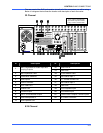
8/16 Channel
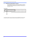
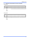
1 2 3 4 5 6 7 8 9 10 11 12 13 14 15 16
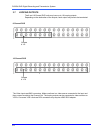
CONTROL
COM2
COM 1
CH 1 in CH 2 in CH 3 in CH 4 in CH 5 in CH 6 in CH 7 in CH 8 in CH 9 in CH 10 in CH 11 in CH 12 in CH 13 in CH 14 in CH 15 in CH 16 in
CH 1 Out CH 2 Out CH 3 Out CH 4 Out CH 5 Out CH 6 Out CH 7 Out CH 8 Out CH 9 Out CH 10 Out CH 11 Out CH 12 Out CH 13 Out CH 14 Out CH 15 Out CH 16 Out
1 2 3 4 5 6 7 8 9 10 11 12 13 14 15 16
COM
SENSOR
BNC A
BNC B
ON
OFF
1CA M ER A 75 TER M 16
ON
OFF
1CA M ER A 75 TER M 16
1 to 2 of the 4 channel audio
input cards may be mounted
in any of the 4 end PCI slots