


12
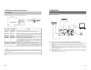
Component Names & Functions
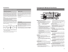
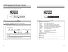
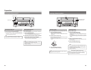
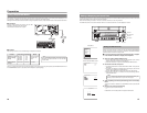
Rear Panel
VIDEO AUDIO
IN
IN
OUT
IN
OUT
CH1
CH2
REMOTE
USB
DV IN/OUT
SIGNAL
LAN
GND
DC 19V
4dB
8dB
INPUT
LEVEL
LINE
Y/C
1
VIDEO LINE IN terminal (BNC)
This terminal allows composite video signals to be input to
the DVD recorder.
In order to select these signals for input, set INPUT SELECT
from the INPUT SELECT MENU screen to LINE.
● SETUP from the SYSTEM MENU screen should be set in
accordance with whether or not this input signal is a setup
signal.
(U-model only)
2
VIDEO Y/C IN terminal (4-pin)
This terminal allows YC separate video signals to be input to
the DVD recorder.
In order to select these signals for input, set INPUT SELECT
from the INPUT SELECT MENU screen to Y/C.
● SETUP from the SYSTEM MENU screen should be set in
accordance with whether or not this input signal is a setup
signal. (U-model only)
● This terminal’s specification (i.e., S1 or S2) can be selected
using Y/C TERMINAL MODE from the RECORDER MENU
(2/2) screen.
3
VIDEO LINE OUT terminal (BNC)
This terminal is used to connect the DVD recorder to a monitor.
● When the DVD recorder is in Stop or Recording mode, the
video input signal is output on the E-E screen as a
composite video signal.
● If the REC button is pressed and held for at least 2 seconds
while the DVD recorder is stopped, the input signal will be
subjected to MPEG encode/decode processing and output
via the VIDEO LINE OUT terminal. This will continue for as
long as the REC button is held, and it allows the DVD
recording quality to be confirmed.
● Playback from the DVD is output as a composite signal
when in Playback mode.
● The Setup Menu, title menu, chapter menus, and other
setting and control screens are displayed on the monitor
connected to this terminal.
●
Status and alarm information is also displayed on-screen.
(The DISPLAY MENU screen can be used to indicate which
items are to be displayed.)
4
AUDIO INPUT LEVEL switch
This switch is used to set the standard level for audio input.
+4dB : The standard level is set to +4 dB.
–8dB : The standard level is set to –8 dB.
12345
6
7
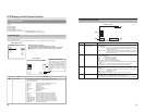
5
AUDIO IN terminals (RCA
× 2)
These terminals allow analog audio signals to be input to the
DVD recorder.
●
In order to select these signals for input, set INPUT SELECT
from the INPUT SELECT MENU screen to LINE or Y/C.
6
AUDIO OUT terminals (RCA × 2)
These terminals allow analog audio signals to be output from
the DVD recorder.
● When the DVD recorder is in Stop or Recording mode, the
audio input signals (i.e., E-E signals) are output via these
terminals.
● Audio from the DVD is output when in Playback mode.
7
DV IN/OUT terminal
This I/O terminal for digital signals conforms with IEEE1394
specifications.
As such, it allows the DVD recorder to be connected to DV
cameras, DV VCRs, and non-linear editors with DV terminals.
● In order to select this terminal
’s audio and video signals for
input, set INPUT SELECT from the INPUT SELECT MENU
screen to DV.
● REMOTE SELECT from the REMOTE MENU screen is
used to select a control method for this terminal as follows.
DV(MASTER) : The DVD recorder operates as the
master device and controls a DV camera
or VCR.
DV(SLAVE) : The DVD recorder operates as a slave
device and is controlled by commands
from a non-linear editor.
DV(TRIGGER) : The DVD recorder performs recording
in response to operation of the trigger
button on a camera capable of DV
triggering (i.e., a GY-DV5000).
13
VIDEO AUDIO
IN
IN
OUT
IN
OUT
CH1
CH2
REMOTE
USB
DV IN/OUT
SIGNAL
LAN
GND
DC 19V
4dB
8dB
INPUT
LEVEL
LINE
Y/C
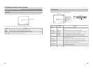
8
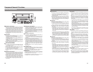
RS-422A REMOTE terminal (D-sub 9-pin male)
This terminal is used to connect the DVD recorder to a VCR
capable of being controlled via RS-422A. RS-422A control of
a VCR using the RS-422A REMOTE terminal is carried out
with the DVD recorder operating in Master mode.
● In order to use this terminal, set REMOTE SELECT from
the REMOTE MENU screen to 9PIN(MASTER).
Video and audio from the VCR can be recorded to a DVD
using commands issued from the REMOTE CONTROL
screen. (
☞ Page 59)
9
LAN terminal (RJ-45)
● When two DVD recorders are used to perform DVD-to-DVD
dubbing, this terminal is connected to both BD-X200s. A
cable of Category 5 or better is required for this connection.
A cross-type Ethernet cable is required when connecting
directly to another BD-X200.
● This terminal is also used when connecting to a PC on
which BD-X200 utility software for operations such as the
creation of the title and chapter menus has been installed.
● Network settings must be carried out using the NETWORK
MENU screen.
0
USB terminals (2)
These terminals are used when connecting the DVD recorder
to USB devices such as a keyboard or mouse.
A keyboard and mouse can be used as an alternative to the
D
VD recorder’s buttons when using setting and control
screens.
The input of text in setting screens is carried out using a
keyboard.
● It is not be possible to operate devices other than a keyboard
or mouse by connecting them to the USB terminal.
● Set KEYBOARD STYLE from the SYSTEM MENU screen
in accordance with the keyboard’s input language.
Recommended manufacturers: Logitech
8
!
@0#
9
$
!
DC IN terminal (2-pin)
This terminal is used to provide DC at 19 V to the DVD
recorder. The DC power cord from the AC adaptor (included)
should be connected here.
@
DC power cord clamp
This clamp secures the DC power cord in place, and it should
always be used to prevent accidental disconnection.
#
SIGNAL GND terminal
This terminal is used to ground signals.
$
Optional-board slot cover
This cover is removed to allow commercially-available optional
boards to be installed.
Note
When power is supplied via this terminal, the OPERATE
indicator on the front panel lights up in red.