


VR-N100U USERS MANUAL
Page 12 of 98 All Items Are Subject To Change Without Notice Feb. 2004 Rev 1.0
2.3.2 Embedded Industrial Server
The engine that runs the VR-N100U security appliance is based on the custom designed fourth generation embedded
industrial server motherboard. The Intel-based processor and memory are preconfigured on the VR-N100U. The motherboard
comes fully equipped with storage in mind with multiple onboard ATAPI/IDE Channels that offers the ability to support large
number of peripherals. In addition to the massive number of ATAPI devices, it can also be equipped with an onboard SCSI
Channel with two less ATAPI Channels. The Adaptec Ultra160-LVD/SE SCSI supports any SCSI-1, SCSI-2, SCSI-3, Narrow,
Ultra, Wide, Ultra Wide, LVD160, and LVD320-based devices. The onboard SCSI offers the ability for VR-N100U customers to
easily expand the total amount of RAID storages. The VR-N100U also comes standard with dual onboard 10/100 Network
Interface Connectors (NIC’s) for providing a higher level of flexibility, connectivity and functionality. LAN1 is designated for the
VR-N100U front-channel for connectivity to the company’s main network backbone while LAN2 is used as the VR-N100U
backchannel for managing up to 16 cameras. For additional expandability, an onboard 32-bit PCI Expansion Slot can to be
utilized for the optional Video Life Cycle Management function of VR-N100U. As most motherboards today come standard with
USB support, the VR-N100U is no different. The board also has the capability to support onboard USB. Finally, thanks to the
optimized and multi-threaded embedded Operating System and intelligent VR-N100U application installed on the non-volatile
flash disk, VR-N100U is able to achieve fastest performance.
2.3.3 Storage Capacity
The main difference between the various 19” 1U VR-N100U Rackmount appliance models will be the amount of online storage
that the customer would like to have. The amount storage capacity will be dictated by the length of time (duration) required to
store the captured video. This calculation will be dictated by the number of cameras managed by VR-N100U (up to 16 per
unit), the resolution setting for each camera, as well as the recording method for each camera. As indicated above, the VR-
N100U will be normally configured with at least four large capacity and fast performance ATAPI hard disk drives. These drives
will be part of a RAID-set, thus it is recommended that they are all of the same make, model and capacity.
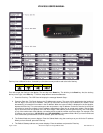
2.3.4 LCD Panel with Keypad and LED Indicators
The VR-N100U appliance is designed to utilize the LCD Display Panel, Keypad and LED Indicators. This LCD Display
supports 2-lines of 16 alphanumeric characters, has four (4) access buttons, and also includes the four (4) LEDs that provide
important status information for various components. These are utilized by the VR-N100U to provide important information
regarding the current status of the appliance. These include the Status Activity, Network Activity (LAN1), 10/100 Network
Connection Status (LAN1), and Device Activity for all ATAPI and SCSI Channels. The phases of the lights provide information
about the operation of the VR-N100U.
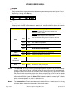
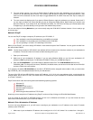
LCD Panel
When the VR-N100U starts up, the LCD display will begin displaying messages. It will keep you informed of the
steps the system is going through during the boot up process and is summarized on the chart below. This
comprehensive display graphically illustrates the steps of each process that can be performed using the LCD
Panel.
The LCD Panel begins by displaying the message Hardware POST with a version number on the second line
(POST stands for Power-On Self-Test). The Status LED (the first indicator light on the left) will display solid red.
As VR-N100U boots the OS (operating system) and detects the drives, those messages will be display on the
Panel. When the boot up process goes into the next phase, the Status LED changes to solid amber and the
version number of the firmware is displayed on the Panel. The system then attempts to acquire an IP address,
checks the drives, and starts networking services. If a DHCP Server is running on the network, VR-N100U
dynamically acquires an IP address. The Status light turns solid green and the default Server Name displays on
the LCD Panel with the IP address on the next line. The Server Name and IP address will continue to display
until an event occurs on the VR-N100U, or the user pushes a key. This is called the Steady State Display, and it
means everything is running. If the VR-N100U did not dynamically acquire an IP address, it will assign itself the
address 10.10.10.10 and the Status light will slowly blink amber. When a VR-N100U comes up tens, it means
that a Static IP address must be assigned to the system before anything else can be done with it. You will need
to go your network admin and get an IP address, the Subnet Mask, and the address of the Default Gateway.