


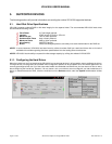
VR-N100U USERS MANUAL
Page 79 of 98 All Items Are Subject To Change Without Notice Feb. 2004 Rev 1.0
NOTE1: “*” The default SCSI ID for the onboard Adaptec LVD160 Chipset is ID #7 with both Parity and Termination Enabled.
NOTE2: Various SCSI devices can be daisy-chained on the SCSI bus, however the bus speed and cable length restrictions
will be governed by the slowest attached SCSI device type.
NOTE3: Proper SCSI etiquette (unique SCSI IDs, SCSI termination (end devices only with Active termination recommended),
proper SCSI cable lengths) must be maintained at all items to ensure the highest performance and reliability.
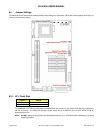
6.1.5. Onboard Dual Ethernet
The VR-N100U board comes standard with dual onboard 10/100 Network Interface Connectors (NICs) for providing a higher
level of flexibility, connectivity and functionality.
NOTE1: LAN1 is designed for use as the VR-N100U front-channel for connectivity to the company’s main network backbone.
NOTE2: LAN2 is designed for use as the VR-N100U backchannel for managing up to 16 cameras and should be connected to
the dedicated “camera” switch on port 17 of the 24-port switch.
6.1.6. PCI Expansion Slot
The VR-N100U board comes standard with an onboard 32-bit PCI Expansion Slot. This Expansion Slot is designed to be
utilized with the optional Video Life Cycle Management function of VR-N100U.
NOTE1: A third party PCI Riser Card may not work with the VR-N100U board.
6.1.7. USB
The board is designed to support dual onboard USB channels.
NOTE: The current version of VR-N100U does not incorporate support for the USB, thus please do not attempt to attach any
USB device to the dual USB ports of the 19” 1U rackmount.
6.1.8. COM Port
The board has a COM port on the rear, however, it is not utilized by VR-N100U. Therefore, please do not attempt to attach any
serial cable or device to it.