


VR-N100U USERS MANUAL
Page 83 of 98 All Items Are Subject To Change Without Notice Feb. 2004 Rev 1.0
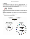
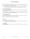
6.5. LED Panel with Keypad and LED Indicators
The VR-N100U appliance is designed to utilize the LCD Display Panel, Keypad and LED Indicators. This LCD Display
supports 2-lines of 16 alphanumeric characters, has four (4) access buttons, and also includes the four (4) LEDs that provide
important status information for various components. These are utilized by the VR-N100U to provide important information
regarding the current status of the appliance. These include the Status Activity, Network Activity (LAN1), 10/100 Network
Connection Status (LAN1), and Device Activity for all ATAPI and SCSI Channels. The phases of the lights provide information
about the operation of the VR-N100U.
6.5.1. LCD Panel
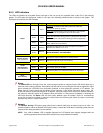
When the VR-N100U starts up, the LCD display will begin displaying messages. It will keep you informed of the steps the
system is going through during the boot up process and is summarized on the chart below. This comprehensive display
graphically illustrates the steps of each process that can be performed using the LCD Panel.
The LCD Panel begins by displaying the message Hardware POST with a version number on the second line (POST stands
for Power-On Self-Test). The Status LED (the first indicator light on the left) will display solid red. As VR-N100U boots the OS
(operating system) and detects the drives, those messages will be display on the Panel. When the boot up process goes into
the next phase, the Status LED changes to solid amber and the version number of the firmware is displayed on the Panel. The
system then attempts to acquire an IP address, checks the drives, and starts networking services. If a DHCP Server is running
on the network, VR-N100U dynamically acquires an IP address. The Status light turns solid green and the default Server
Name displays on the LCD Panel with the IP address on the next line. The Server Name and IP address will continue to
display until an event occurs on the VR-N100U, or the user pushes a key. This is called the Steady State Display, and it
means everything is running. If the VR-N100U did not dynamically acquire an IP address, it will assign itself the address
10.10.10.10 and the Status light will slowly blink amber. When a VR-N100U comes up tens, it means that a Static IP address
must be assigned to the system before anything else can be done with it. You will need to go your network admin and get an
IP address, the Subnet Mask, and the address of the Default Gateway.
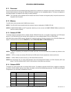
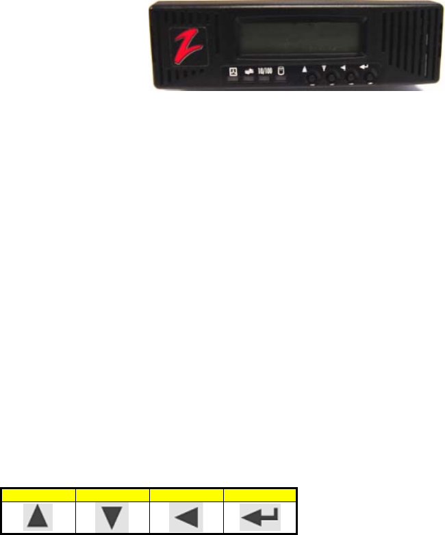
6.5.2. Keypad
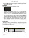
Each key has a different function, illustrated by a directional arrow just above and to the left of the key. From left to right, the
first key is the Up key. The next key is the Down key. The third key is the Back key. And, the last key, the key on the right, is
the Enter key.
Up Down Back Enter