


VR-N100U USERS MANUAL
Page 13 of 98 All Items Are Subject To Change Without Notice Feb. 2004 Rev 1.0
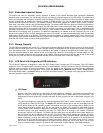
Keypad
Each key has a different function, illustrated by a directional arrow just above and to the left of the key. From left
to right, the first key is the Up key. The next key is the Down key. The third key is the Back key. And, the last
key, the key on the right, is the Enter key.
Up Down Back Enter
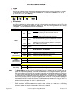
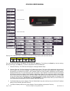
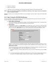
LED Indicators
The LEDs are identified by a keyword above each light on the unit and by the complete name of the LED in the
following graphic. The LED lights can flash green, amber, or red, each color indicating a different state or activity
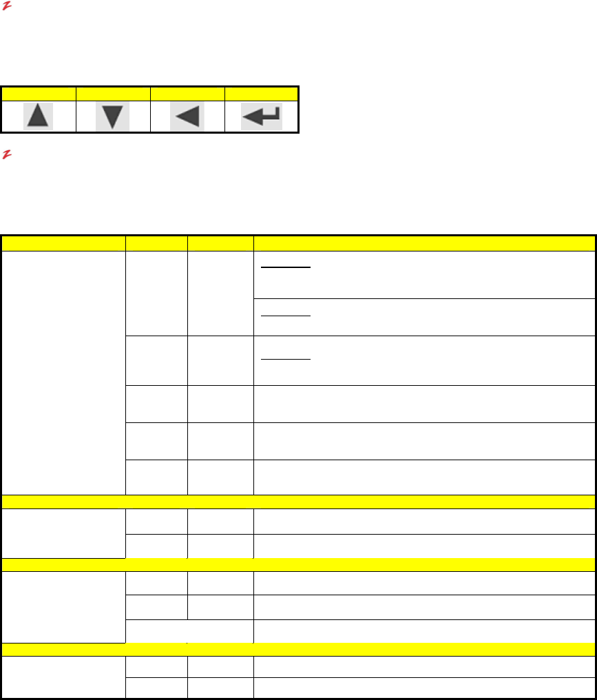
of the system. The chart below summarizes the LED indicators.
LED Label Color Aspect Description
Power-On
: Solid Red during power-on indicates a self-test. When
the self-test is completed, the LED transitions to amber and
continues the power-on process.
Red Solid
Power-Off
: Solid Red during power-off indicates a safe halt, after
which power can be safely turned off on the VR-N100U
Amber Solid
Power-On
: Solid Amber during power-on indicates that VR-N100U
has completed the self-test and is booting the OS and application.
Green Solid
Indicates that VR-N100U is completely initialized. It has acquired
and IP address and is operational.
Amber Flashing
Indicates that VR-N100U was unable to acquire an IP address. It
defaults to the address 10.10.10.10.
Status
Green/
Amber
Blinking
Indicated that VR-N100U is reflashing the firmware.
NEVER INTERRUPT THIS PROCESS!!!
Green Flashing Indicates that network traffic from an external source
Network
Network Activity
(LAN1-Backbone)
Amber Flashing Indicates that the VR-N100U is transmitting
Amber Solid Your network speed is 10 Mbps.
Green Solid Your network speed is 100 Mbps.
10/100
Network Speed
(LAN1-Backbone)
No Light Indicates that there is no network link visible to the VR-N100U
Green Flashing An IDE drive is reading or writing data.
Drive
Drive Activity
Red Flashing A SCSI drive is reading or writing data.
Status: The Status LED, the first light on the left, cycles through its power-on sequence as the VR-N100U boots up.
It starts out solid red during self-test. Solid amber indicates the server is booting the OS and the application.
Solid green indicates the VR-N100U has successfully powered on and dynamically acquired an IP address.
The Status light will remain solid green throughout normal operation. If the Status light slowly blinks amber,
VR-N100U has failed to dynamically acquire an IP address. You must simply use one of the four methods
outlined in the manual to manually acquire an IP address. When VR-N100U is in the process of updating or
reflashing the VR-N100U firmware, the Status LED will flash quickly between green and amber. Under no
circumstances should the process be cancelled or power be removed from the unit during the reflash. A
partial or terminated operation may result in a dysfunctional unit.
Network: The Network Activity LED flashes green when there is network traffic from an external source on LAN1, the
network backbone. When the Network LED flashes amber, it means the VR-N100U is transmitting
information between the cameras, storage and/or clients over the network.