


Troubleshooting
6-7
9123-A2-GB20-10
July 2000
Alarms
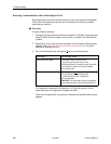
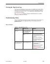
The following table describes the alarm conditions that will generate an SNMP
trap for a physical interface, and the frame relay LMIs and DLCIs. These alarm
conditions also generate Health and Status messages seen on the System and
Test Status screen.
Main Menu
→
Status
→
System and Test Status
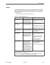
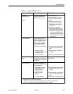
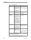
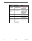
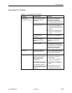
Table 6-1. Alarm Conditions (1 of 4)
Alarm Condition
What It Indicates What To Do
AIS at Network 1 An Alarm Indication Signal
(AIS) is being received by
the interface. AIS is an
unframed, all ones signal.
For the network interface, report
the problem to your T1 service
provider.
CTS down to
Port-1
Device
The CTS control lead on
the device’s interface is off.
Check DTR and RTS from
Port-1.
H Verify that the port is enabled.
H Check DTR from the user data
port.
DLCI
nnnn
Down,
frame relay link
1,2
The DLCI for the specified
frame relay link is down.
Verify that the network LMI is up.
If it is, contact your network
service provider.
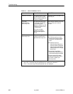
DTR Down from
Port-1 Device
The DTR control lead on
the device connected to the
specified port is off. This
message applies to data
ports that act as DCEs.
Examine the attached DTE and
cable connected to the system’s
port.
H Check that the port cable is
securely attached at both
ends.
H Check the status of the
attached equipment.
EER at Network
1 The error rate of the
received network signal
exceeds the currently
configured threshold. This
condition only occurs if the
network interface is
configured for ESF framing.
This condition clears when
the error rate falls below the
threshold value, which may
take up to 15 minutes.
H Verify that the network cable is
securely attached at the
network interface.
H Contact your network provider.
1
nnnn
indicates a DLCI number of 16 through 1007.
2
frame relay link
is one of the following:
– Net1-FR1. The frame relay link specified for the network interface, Network 1.
– Port-1. The frame relay link associated with the user data port.