


Configuration
3-57
9123-A2-GB20-10
July 2000
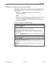
Configuring the Ethernet Port
Select Ethernet Port from the Management and Communication menu, or
Ethernet Port Options Screen from the Easy Install screen, to configure the
Ethernet port (see Table 3-15).
Main Menu
→
Configuration
→
Management and Communication
→
Ethernet Port
Main Menu
→
Easy Install
→
Ethernet Port Options Screen
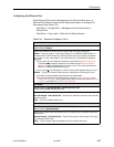
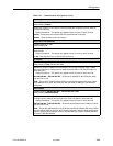
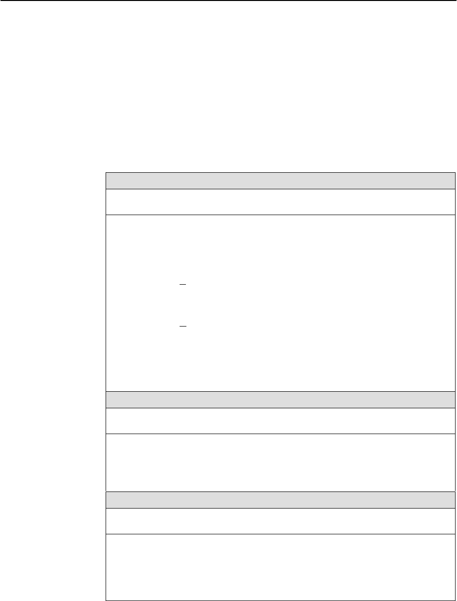
Table 3-15. Ethernet Port Options (1 of 2)
Interface Status
Possible Settings: Enable, Disable
Default Setting: Disable
Determines whether the Ethernet port is being used and can be configured.
Enable – The port is active. It can receive Version 2 or IEEE 802.3 MAC frames, or
transmit Version 2 MAC frames only. When the Ethernet port is enabled, the Would
you like to set the Node’s IP Destination to Ethernet? prompt is
displayed.
H If you select Yes, the Default IP Destination (see Table 3-9, Node IP Options)
is automatically changed to Ethernet, so the Ethernet port’s Default Gateway
Address is used for packets that do not have a route. This is required when the
NMS is on a different subnet than the unit.
H If you select No, the COM port or a PVC will be used for packets without a route.
Disable – The port is not active. When the port is disabled, the following will occur:
H No alarms or traps configured for the port will be generated.
H All port uses that refer to the Ethernet port, like the Default IP Destination and
Initial Route Destination, will be reset to their default values (see Table 3-9, Node
IP Options, and Table 3-14, SNMP Traps Options).
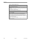
IP Address
Possible Settings: 001.000.000.000 – 223.255.255.255, Clear
Default Setting: Clear (000.000.000.000)
Specifies the IP address needed to access the Ethernet port.
001.000.000.000 – 223.255.255.255 – Shows the IP address for the port, which can be
viewed or edited.
Clear – Fills the IP address with zeros.
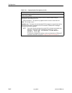
Subnet Mask
Possible Settings: 000.000.000.000 – 255.255.255.255, Clear
Default Setting: 000.000.000.000
Specifies the subnet mask associated with the IP address that is needed to access the
Ethernet port.
000.000.000.000 – 255.255.255.255 – Set the Ethernet port’s subnet mask. The range
for each byte is 000 to 255.
Clear – Fills the subnet mask associated with the IP address with zeros.